STEERING COLUMN ASSEMBLY > REMOVAL |
| 1. PRECAUTION |
| 2. DISCONNECT CABLE FROM NEGATIVE BATTERY TERMINAL |
| 3. PLACE FRONT WHEELS FACING STRAIGHT AHEAD |
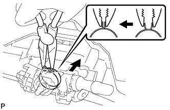
| 4. REMOVE STEERING PAD ASSEMBLY |
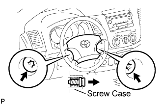 |
Straighten the front wheels.
Using a T30 "torx" socket, loosen the 2 screws until the groove along each screw circumference catches on the screw case.
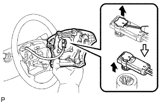 |
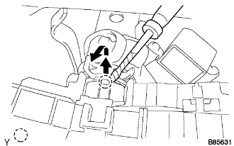
Pull out the steering pad from the steering wheel and support the steering pad with one hand as shown in the illustration.
Using a screwdriver, disconnect the airbag connector.
Disconnect the horn connector and remove the steering pad.
| 5. REMOVE STEERING WHEEL ASSEMBLY |
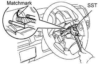 |
Remove the steering wheel set nut.
Place matchmarks on the steering wheel and main shaft.
Using SST, remove the steering wheel.
| 6. REMOVE STEERING COLUMN LOWER COVER |
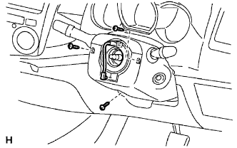 |
Remove the 3 screws and cover lower.
| 7. REMOVE STEERING COLUMN UPPER COVER |
| 8. REMOVE INSTRUMENT CLUSTER FINISH PANEL |
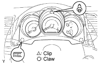 |
Remove the clip.
Detach the 2 claws and remove the panel.
| 9. REMOVE SPIRAL CABLE SUB-ASSEMBLY |
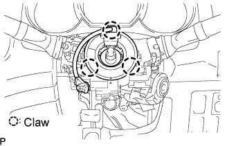 |
Disconnect the connectors from the spiral cable.
Detach the 3 claws and remove the spiral cable.
| 10. REMOVE WIPER AND WASHER SWITCH ASSEMBLY |
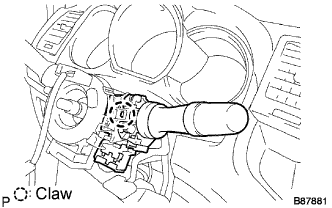 |
Disconnect the connectors.
Detach the claw and remove the wiper switch.
| 11. REMOVE HEADLIGHT DIMMER SWITCH ASSEMBLY |
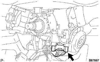 |
Disconnect the connector.
 |
Using needle-nose pliers, remove the band clamp as shown in the illustration.
 |
Using a screwdriver, detach the claws and remove the switch.
| 12. REMOVE INSTRUMENT PANEL SUB-ASSEMBLY UPPER |
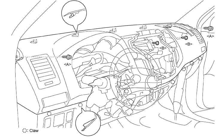
Remove the 2 bolts <A> and 2 screws <B>.
Pull up the instrument panel to detach the 8 claws.
Disconnect all connectors.
Remove the instrument panel.
| 13. REMOVE INSTRUMENT PANEL SUB-ASSEMBLY LOWER |
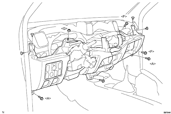
Using a clip remover, remove the 4 clips from the duct and instrument panel.
Remove the 2 bolts <A> and nut <G>.
Remove the 3 screws <F>.
Disconnect all connectors and detach all clamps.
Remove the hood lock control cable lever and fuel lid control cable lever.
Remove the instrument panel.
| 14. DISCONNECT STEERING SLIDING YOKE |
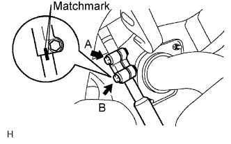 |
Loose the bolt labeled A.
Make matchmarks on the steering yoke and steering intermediate shaft.
Remove the bolt labeled B.
| 15. DISCONNECT CONNECTOR |
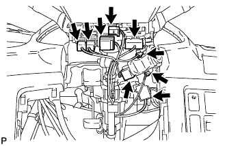 |
Disconnect the 9 connectors and wire harness clamps from the steering column.
| 16. REMOVE STEERING COLUMN HOLE COVER SUB-ASSEMBLY |
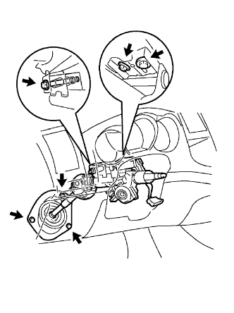 |
Remove the 3 bolts and cover.
| 17. REMOVE STEERING COLUMN ASSEMBLY |
Remove the 3 bolts and pull out the steering column together with the steering sliding w/ coupling yoke.
