SFI SYSTEM > Variable Resistor Circuit |
| 1.CHECK CO/HC |
 |
Warm up the engine to normal operating temperature.
Turn all accessories OFF.
Connect all vacuum lines properly.
Connect the tachometer.
Check ignition timing correctly.
Check idle speed correctly.
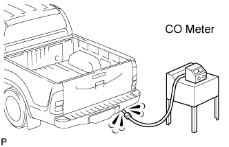
Check that the CO meter is properly calibrated.
Race the engine at 2,500 rpm about 2 minutes.
Insert a tester probe at least 40 cm (1.3 ft.) into the tailpipe.
Measure the concentration with 1 to 3 minutes after racing the engine to allow the concentration to stabilize.
|
| ||||
| NG | |
| 2.ADJUST CO CONCENTRATION |
 |
Put the vehicle in the same condition as the previous step (CHECK CO/HC).
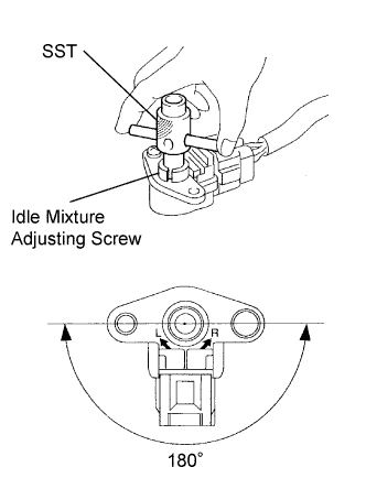
Using SST, adjust the idle mixture by turning the idle mixture adjusting screw in the variable resistor.
| Result | Proceed |
| Concentration: 1.5 +- 0.5% | B |
| Change in CO concentration | C |
| No change in CO concentration | A |
|
| ||||
|
| ||||
| A | |
| 3.INSPECT VARIABLE RESISTOR |
 |
Measure the resistance according to the value(s) in the table below.
| Tester Connection | Specified Condition |
| 1 - 2 | 3.5 to 6.5 Ω |
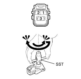
While fully turning the idle mixture adjusting screw clockwise and counterclockwise using SST, measure the resistance.
| Tester Connection | Specified Condition |
| 2 - 3 | Voltage changes from approximately 5 to 0 kΩ |
|
| ||||
| OK | |
| 4.CHECK ECM (VAF VOLTAGE) |
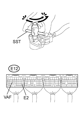 |
Turn the ignition switch ON.
While fully turning the idle mixture adjusting screw clockwise and counterclockwise slowly using SST, measure the voltage.
| Tester Connection | Specified Condition |
| VAF (E12-25) - E2 (E12-28) | Voltage changes smoothly from 0 to approximately 5 V (does not change suddenly) |
|
| ||||
| NG | |
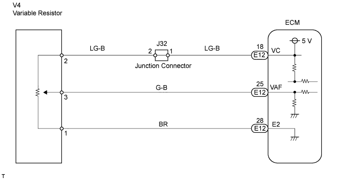
| 5.CHECK HARNESS AND CONNECTOR (VARIABLE RESISTOR - ECM) |
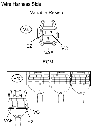 |
Disconnect the V4 variable resistor connector.
Disconnect the E12 ECM connector.
Measure the resistance according to the value(s) in the table below.
| Tester Connection | Specified Condition |
| VC (V4-2) - VC (E12-18) | Below 1 Ω |
| VAF (V4-3) - VAF (E12-25) | Below 1 Ω |
| E2 (V4-1) - E2 (E12-28) | Below 1 Ω |
| Tester Connection | Specified Condition |
| VC (V4-2) or VC (E12-18) - Body ground | 10 kΩ or higher |
| VAF (V4-3) or VAF (E12-25) - Body ground | 10 kΩ or higher |
|
| ||||
| OK | ||
| ||
