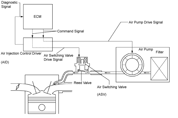
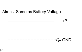
AID Diagnostic Signal Waveform
| ECM Command
| DTC
(ECM Output)
| Suspected Trouble Area
|
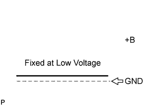
100% Duty Ratio
See waveform 1
| Any Air Injection (AI) System operation
| P1613
| - Open in diagnostic signal circuit
- Air Injection Control Driver (AID)
- Open in AID +B circuit (AID power source)
- Short between +B circuit and diagnostic signal circuit
|
0% Duty Ratio
See waveform 2
| AI System: ON
(Air pump ON, ASV ON)
| P1613
| - Open or short in air pump or Air Switching Valve (ASV) command signal circuit (ECM - AID)
- Open in AID ground circuit
- Short between diagnostic signal circuit and body ground
- AID
- ECM
|
AI System: OFF
(Air pump OFF, ASV OFF)
| -
| - Normal
|
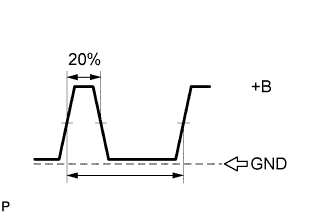
20% Duty Ratio
See waveform 3
| Air Pump: ON
| P0418
| - Short between air pump drive circuit and body ground
- Harness & connector (AID - Pump)
- Air Pump
- AID
- ECM
|
Air Pump: OFF
| P0418
| - Open in air pump drive circuit (AID - Pump), or short between air pump drive circuit and +B
- Harness & connector (AID - Pump)
- Air Pump
- AID
- ECM
|
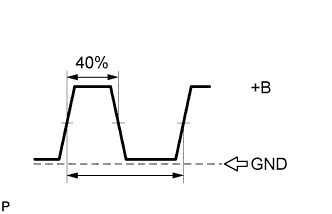
40% Duty Ratio
See waveform 4
| ASV: ON
| P0412
| - Short between ASV drive circuit and body ground
- Harness & connector (AID - ASV)
- ASV
- AID
- ECM
|
ASV: OFF
| P0412
| - Open in ASV drive circuit (AID - ASV), or short between ASV drive circuit and +B
- Harness & connector (AID - ASV)
- AID
- ASV
- ECM
|
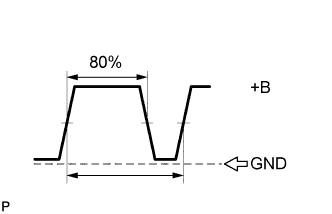
80% Duty Ratio
See waveform 5
| AI System: OFF
(Air pump OFF, ASV OFF)
| P1613
| - AID
- ECM
|
AI System: ON
(Air pump ON, ASV ON)
| -
| - Normal
|
Excluding Above
(excluding 0, 20, 40, 80, 100% duty)
| -
| P1613
| - AID
- Open in AID ground circuit
|