DTC P2A00 A/F Sensor Circuit Slow Response (Bank 1 Sensor 1) |
| DTC No. | DTC Detection Conditions | Trouble Areas |
| P2A00 | Calculated value for air-fuel ratio (A/F) sensor response rate deterioration level is less than threshold |
|
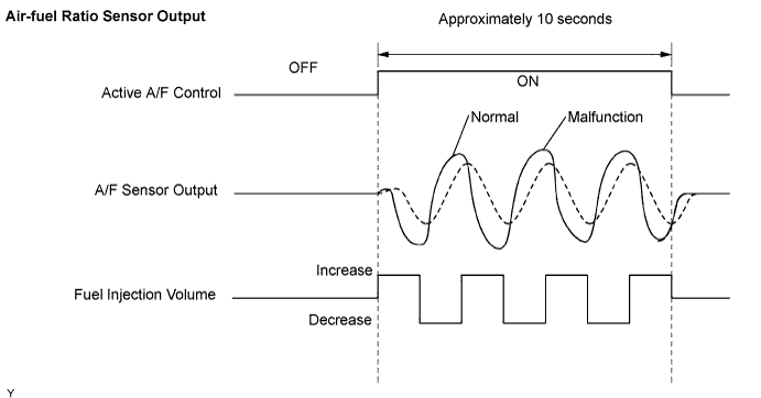
| Tester Display (Sensor) | Injection Volume | Status | Voltage |
| AFS B1 S1 (A/F) | +25% | Rich | Less than 3.0 V |
| AFS B1 S1 (A/F) | -12.5% | Lean | More than 3.35 V |
| O2S B1 S2 (HO2) | +25% | Rich | More than 0.55 V |
| O2S B1 S2 (HO2) | -12.5% | Lean | Less than 0.4 V |
| Case | A/F Sensor (Sensor 1) Output Voltage | HO2 Sensor (Sensor 2) Output Voltage | Main Suspected Trouble Areas | ||
| 1 | Injection Volume +25% -12.5% |  | Injection Volume +25% -12.5% | | - |
| Output Voltage More than 3.35 V Less than 3.0 V |  | Output Voltage More than 0.55 V Less than 0.4 V |  | ||
| 2 | Injection Volume +25% -12.5% | | Injection Volume +25% -12.5% | |
|
| Output Voltage Almost no reaction |  | Output Voltage More than 0.55 V Less than 0.4 V | | ||
| 3 | Injection Volume +25% -12.5% | | Injection Volume +25% -12.5% | |
|
| Output Voltage More than 3.35 V Less than 3.0 V | | Output Voltage Almost no reaction | | ||
| 4 | Injection volume +25% -12.5% | | Injection Volume +25% -12.5% | |
|
| Output Voltage Almost no reaction | | Output Voltage Almost no reaction | | ||
| 1.CHECK OTHER DTC OUTPUT (IN ADDITION TO A/F SENSOR DTC) |
Connect the intelligent tester to the DLC3.
Turn the ignition switch ON and turn the intelligent tester ON.
Select the following menu items: Powertrain / Engine and ECT / DTC.
Read DTCs.
| Display (DTC Output) | Proceed to |
| P2A00 | A |
| P2A00 and other DTCs | B |
|
| ||||
| A | |
| 2.INSPECT AIR FUEL RATIO SENSOR (HEATER RESISTANCE) |
 |
Disconnect the A18 sensor connector.
Measure the resistance of the sensor.
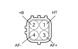
| Tester Connection | Condition | Specified Condition |
| 1 (HT) -2 (+B) | 20°C (68°F) | 1.8 to 3.4 Ω |
| 1 (HT) -4 (AF-) | Always | 10 kΩ or higher |
|
| ||||
| OK | |
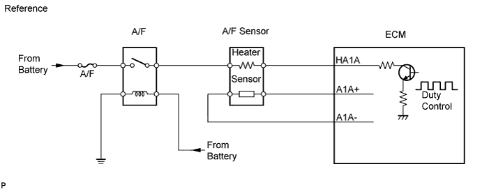
| 3.CHECK WIRE HARNESS (A/F SENSOR - ECM) |
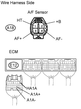 |
Disconnect the A18 A/F sensor connector.
Turn the ignition switch ON.
Measure the voltage of the wire harness side connector.
| Tester Connection | Specified Condition |
| A18-2 (+B) - Body ground | 9 to 14 V |
Turn the ignition switch OFF.
Disconnect the E12 ECM connector.
Measure the resistance of the wire harness side connectors.
| Tester Connection | Specified Condition |
| A18-1 (HT) - E12-1 (HA1A) | Below 1 Ω |
| A18-3 (AF+) - E12-21 (A1A+) | Below 1 Ω |
| A18-4 (AF-) - E12-31 (A1A-) | Below 1 Ω |
| A18-1 (HT) or E12-1 (HA1A) - Body ground | 10 kΩ or higher |
| A18-3 (AF+) or E12-21 (A1A+) - Body ground | 10 kΩ or higher |
| A18-4 (AF-) or E12-31 (A1A-) - Body ground | 10 kΩ or higher |
|
| ||||
| OK | |
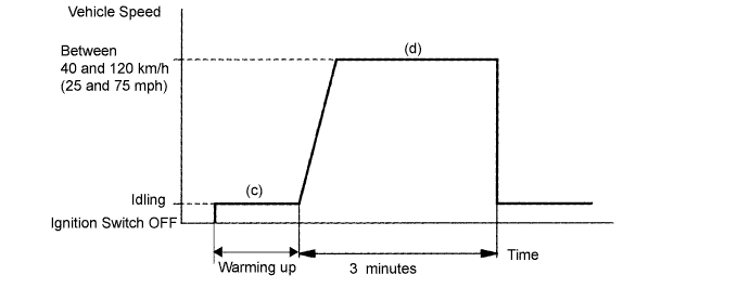
| 4.PERFORM CONFIRMATION DRIVING PATTERN |
| NEXT | |
| 5.CHECK IF DTC OUTPUT RECURS |
Connect the intelligent tester to the DLC3.
Turn the ignition switch ON and turn the intelligent tester ON.
Select the following menu items: Powertrain / Engine and ECT/ DTC.
Read DTCs.
| Display (DTC Output) | Proceed to |
| P2A00 | A |
| No output | B |
|
| ||||
| A | |
| 6.REPLACE AIR FUEL RATIO SENSOR |
| NEXT | |
| 7.PERFORM CONFIRMATION DRIVING PATTERN |
| NEXT | |
| 8.CHECK IF DTC OUTPUT RECURS |
Connect the intelligent tester to the DLC3.
Turn the ignition switch ON and turn the intelligent tester ON.
Select the following menu items: Powertrain / Engine and ECT / DTC.
Read DTCs.
| Display (DTC Output) | Proceed to |
| No output | A |
| P2A00 | B |
|
| ||||
| A | ||
| ||
