DTC P0037 Oxygen Sensor Heater Control Circuit Low (Bank 1 Sensor 2) |
DTC P0038 Oxygen Sensor Heater Control Circuit High (Bank 1 Sensor 2) |
| DTC No. | DTC Detection Condition | Trouble Area |
| P0037 | Heated current is 0.3 A or less when heater operates (1 trip detection logic) |
|
| P0038 | Heated current exceeds 2 A when heater operates (1 trip detection logic) |
|
| 1.INSPECT HEATED OXYGEN SENSOR (HEATER RESISTANCE) |
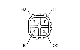 |
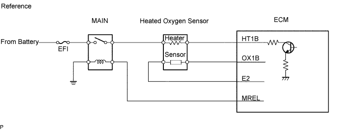
Disconnect the H7 sensor connector.
Measure the resistance of the heated oxygen sensor.
| Tester Connection | Condition | Specified Condition |
| 1 (HT) - 2 (+B) | 20°C (68°F) | 11 to 16 Ω |
| 1 (HT) - 4 (E) | Always | 10 kΩ or higher |
|
| ||||
| OK | |
| 2.INSPECT INTEGRATION RELAY (MAIN RELAY) |
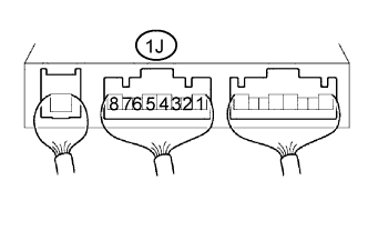 |
Remove the integration relay from the engine room junction block.
Measure the voltage of the MAIN relay.
| Tester Connection | Condition | Specified Condition |
| 1J-5 - Body ground | Ignition switch ON | 10 to 14 V |
|
| ||||
| OK | |
| 3.INSPECT ECM (HT1B VOLTAGE) |
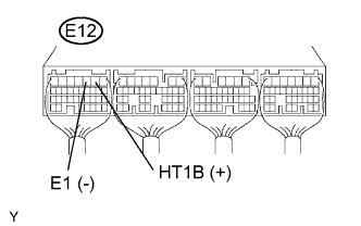 |
Turn the ignition switch ON.
Measure the voltage of the E12 ECM connector.
| Tester Connection | Specified Condition |
| E12-2 (HT1B) - E11-3 (E1) | 9 to 14 V |
|
| ||||
| NG | |
| 4.CHECK WIRE HARNESS (HEATED OXYGEN SENSOR - ECM AND INTEGRATION RELAY) |
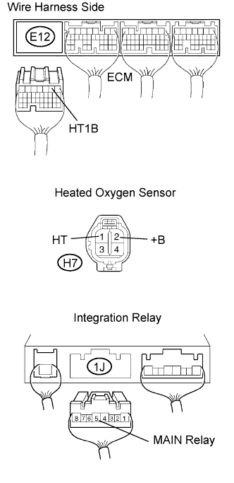 |
Disconnect the H7 sensor connector.
Disconnect the E12 ECM connector.
Disconnect the 1J connector from the engine room junction block.
Measure the resistance of the wire harness side connectors.
| Tester Connection | Specified Condition |
| H7-1 (HT) - E12-2 (HT1B) | Below 1 Ω |
| H7-2 (+B) - 1J-5 | Below 1 Ω |
| H7-1 (HT) or E12-2 (HT1B) - Body ground | 10 kΩ or higher |
| H7-2 (+B) or 1J-5 - Body ground | 10 kΩ or higher |
|
| ||||
| OK | ||
| ||
