DTC P0300 Random / Multiple Cylinder Misfire Detected |
DTC P0301 Cylinder 1 Misfire Detected |
DTC P0302 Cylinder 2 Misfire Detected |
DTC P0303 Cylinder 3 Misfire Detected |
DTC P0304 Cylinder 4 Misfire Detected |
| DTC No. | DTC Detection Condition | Trouble Area |
| P0300 | Misfiring of random cylinders is detected |
|
| P0301 P0302 P0303 P0304 | Misfiring of each cylinder is detected |
|
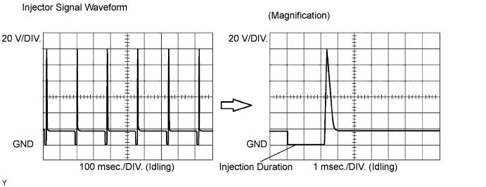
| Tool Setting | Condition |
| 20 V / DIV., 100 or 1 msec. / DIV. | Idling |
| Engine Speed | Time |
| Idling | 3 minutes 30 seconds or more |
| 1,000 rpm | 3 minutes or more |
| 2,000 rpm | 1 minute 30 seconds or more |
| 3,000 rpm | 1 minute or more |
| 1.CHECK OTHER DTC OUTPUT (IN ADDITION TO MISFIRE DTCS) |
Connect the intelligent tester to the DLC3.
Turn the ignition switch ON.
Turn the tester ON.
On the tester, select the following menu items: Powertrain / Engine and ECT / DTC.
Read DTCs.
| Display (DTC Output) | Proceed to |
| One or more of P0300, P0301, P0302, P0303 and P0304 | A |
| One or more of P0300, P0301, P0302, P0303 and P0304, and other DTCs | B |
|
| ||||
| A | |
| 2.READ VALUE OF DATA LIST (MISFIRE RPM, MISFIRE LOAD) |
Connect the intelligent tester to the DLC3.
Turn the ignition switch ON and turn the tester ON.
Select the following menu items: Powertrain / Engine and ECT / Data List / Misfire RPM and Misfire Load.
Read and note the Misfire RPM and Misfire Load (engine load) values.
| NEXT | |
| 3.CHECK PCV HOSE |
|
| ||||
| OK | |
| 4.CHECK MISFIRE COUNT (CYL #1, #2, #3, #4) |
| Misfire Count | Proceed to |
| One or two cylinders have misfire counts | A |
| Three cylinders or more have misfire counts | B |
|
| ||||
| A | |
| 5.CHECK SPARK PLUG |
Remove the ignition coil assembly.
Remove the spark plug.
Check the spark plug type.
| Supplier | Type |
| DENSO | K20HR-U11 |
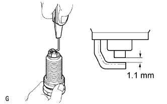 |
Check the spark plug electrode gap.
Check the electrode for carbon deposits.
|
| ||||
| OK | |
| 6.CHECK FOR SPARKS AND IGNITION |
Perform a spark test.
Install the spark plug to the ignition coil, and connect the ignition coil connector.
Disconnect the injector connector.
Ground the spark plug.
Check if sparks occur while the engine is being cranked.
|
| ||||
| OK | |
| 7.CHECK CYLINDER COMPRESSION PRESSURE OF MISFIRING CYLINDER |
Measure the cylinder compression pressure of the misfiring cylinder (Click here).
|
| ||||
| NG | ||
| ||
| 8.CHANGE NORMAL SPARK PLUG AND CHECK SPARK OF MISFIRING CYLINDER |
Change the installed spark plug to a spark plug that functions normally.
Perform a spark test.
Install the spark plug to the ignition coil, and connect the ignition coil connector.
Disconnect the injector connector.
Ground the spark plug.
Check if sparks occur while the engine is being cranked.
|
| ||||
| OK | ||
| ||
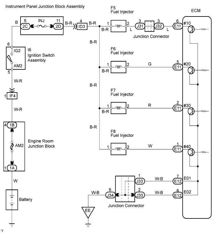
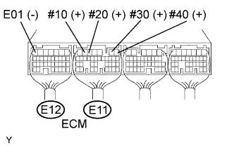
| 9.INSPECT ECM TERMINAL OF MISFIRING CYLINDER (#10, #20, #30, #40 VOLTAGE) |
 |
Turn the ignition switch ON.
Measure the voltage of the E11 and E12 ECM connectors.
| Tester Connection | Specified Condition |
| E11-6 (#10) - E12-7 (E01) | 9 to 14 V |
| E11-5 (#20) - E12-7 (E01) | 9 to 14 V |
| E11-2 (#30) - E12-7 (E01) | 9 to 14 V |
| E11-1 (#40) - E12-7 (E01) | 9 to 14 V |
|
| ||||
| NG | |
| 10.CHECK HARNESS AND CONNECTOR (INJECTOR - ECM) |
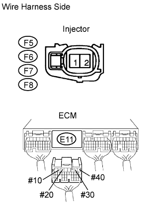 |
Check the wire harness between the injector and ECM.
Disconnect the F5, F6, F7 and F8 injector connectors.
Disconnect the E11 connector.
Measure the resistance of the wire harness side connectors.
| Tester Connection | Specified Condition |
| F5-2 - E11-6 (#10) | Below 1 Ω |
| F6-2 - E11-5 (#20) | Below 1 Ω |
| F7-2 - E11-2 (#30) | Below 1 Ω |
| F8-2 - E11-1 (#40) | Below 1 Ω |
| F5-2 or E11-6 (#10) - Body ground | 10 kΩ or higher |
| F6-2 or E11-5 (#20) - Body ground | 10 kΩ or higher |
| F7-2 or E11-2 (#30) - Body ground | 10 kΩ or higher |
| F8-2 or E11-1 (#40) - Body ground | 10 kΩ or higher |
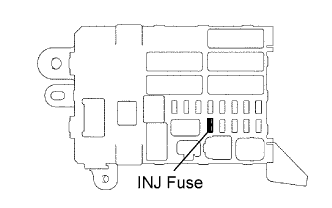 |
Inspect the INJ fuse.
Remove the INJ fuse from the instrument panel junction block.
Measure the resistance of the INJ fuse.
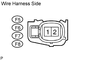 |
Measure the voltage of the injector connectors.
Disconnect the F5, F6, F7 and F8 injector connectors.
Turn the ignition switch ON.
Measure the voltage of the wire harness side connectors.
| Tester Connection | Specified Condition |
| F5-1 - Body ground | Between 11 and 14 V |
| F6-1 - Body ground | Between 11 and 14 V |
| F7-1 - Body ground | Between 11 and 14 V |
| F8-1 - Body ground | Between 11 and 14 V |
|
| ||||
| OK | |
| 11.CHECK FUEL INJECTOR OF MISFIRING CYLINDER |
Check the injector injection. Check that fuel volume is not too high or too low, and that the injection pattern is not poor (Click here).
|
| ||||
| OK | |
| 12.CHECK AIR INDUCTION SYSTEM |
Check the air induction system for vacuum leakage.
|
| ||||
| OK | |
| 13.CHECK VALVE TIMING |
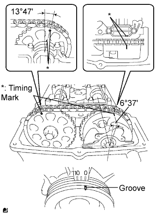 |
Remove the cylinder head cover.
Turn the crankshaft to align the timing marks of the crankshaft.
Align the groove of the crankshaft pulley with the "0" position.
Confirm whether the timing marks of the camshaft pulley and cylinder head cover are facing each other.
If the timing marks are not facing each other, turn the crankshaft clockwise by 360°. Confirm again if the timing marks are facing each other.
|
| ||||
| OK | |
| 14.CHECK FUEL PRESSURE |
Check the fuel pressure (Click here).
|
| ||||
| OK | |
| 15.READ VALUE OF DATA LIST (COOLANT TEMP) |
Connect the intelligent tester to the DLC3.
Turn the ignition switch ON.
Turn the tester ON.
On the tester, select the following menu items: Powertrain / Engine and ECT / Data List / Coolant Temp.
Read the Coolant Temp value twice, when the engine is both cold and warmed up.
|
| ||||
| OK | |
| 16.READ VALUE OF DATA LIST (MAF) |
Connect the intelligent tester to the DLC3.
Turn the ignition switch ON.
Turn the tester ON.
On the tester, select the following menu items: Powertrain / Engine and ECT / Data List / MAF and Coolant Temp.
Allow the engine to idle until the Coolant Temp value reaches 75 °C (167 °F) or more.
Read the MAF with the engine in an idling condition and at an engine speed of 2,500 rpm.
|
| ||||
| OK | ||
| ||
