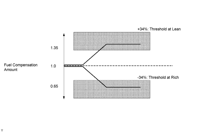
DTC P0171 System Too Lean (Fuel Trim) |
DTC P0172 System Too Rich (Fuel Trim) |
| DTC No. | DTC Detection Condition | Trouble Area |
| P0171 | When air-fuel feedback is stable after warming up engine, fuel trim is considerably in error on lean side (2 trip detection logic) |
|
| P0172 | When air-fuel feedback is stable after warming up engine, fuel trim is considerably in error on rich side (2 trip detection logic) |
|
| Tester Display (Sensor) | Injection Volume | Status | Voltage |
| AFS B1 S1 (A/F) | + 25% | Rich | Less than 3.0 V |
| AFS B1 S1 (A/F) | - 12.5% | Lean | More than 3.35 V |
| O2S B1 S1 (HO2) | + 25% | Rich | More than 0.55 V |
| O2S B1 S1 (HO2) | - 12.5% | Lean | Less than 0.4 V |
| Case | A/F Sensor (Sensor 1) Output Voltage | HO2 Sensor (Sensor 2) Output Voltage | Main Suspected Trouble Areas | ||
| 1 | Injection Volume +25% -12.5% |  | Injection Volume +25% -12.5% | | - |
| Output Voltage More than 3.35 V Less than 3.0 V |  | Output Voltage More than 0.55 V Less than 0.4 V |  | ||
| 2 | Injection Volume +25% -12.5% | | Injection Volume +25% -12.5% | |
|
| Output Voltage Almost no reaction |  | Output Voltage More than 0.55 V Less than 0.4 V | | ||
| 3 | Injection Volume +25% -12.5% | | Injection Volume +25% -12.5% | |
|
| Output Voltage More than 3.35 V Less than 3.0 V | | Output Voltage Almost no reaction | | ||
| 4 | Injection volume +25% -12.5% | | Injection Volume +25% -12.5% | |
|
| Output Voltage Almost no reaction | | Output Voltage Almost no reaction | | ||
| 1.CHECK ANY OTHER DTCS OUTPUT (IN ADDITION TO DTC P0171 OR P0172) |
Connect the intelligent tester to the DLC3.
Turn the ignition switch ON and turn the tester ON.
Select the following menu items: Powertrain / Engine and ECT / DTC.
Read DTCs.
| Display (DTC Output) | Proceed to |
| P0171 or P0172 | A |
| P0171 or P0172 and other DTCs | B |
|
| ||||
| A | |
| 2.CHECK PCV HOSE |
|
| ||||
| OK | |
| 3.CHECK AIR INDUCTION SYSTEM |
Check the air induction system for vacuum leakage.
|
| ||||
| OK | |
| 4.PERFORM ACTIVE TEST (A/F CONTROL) |
Connect the intelligent tester to the DLC3.
Start the engine and turn the tester ON.
Warm up the engine at an engine speed of 2,500 rpm for approximately 90 seconds.
On the tester, select the following menu items: Powertrain / Engine and ECT / Active Test / A/F Control.
Perform the A/F Control operation with the engine in an idling condition (press the right or left button to change the fuel injection volume).
Monitor the output voltage of A/F and HO2 sensors (AFS B1 S1 and O2S B1 S2) displayed on the tester.
| Tester Display (Sensor) | Injection Volume | Status | Voltage |
| AFS B1 S1 (A/F) | + 25% | Rich | Less than 3.0 V |
| AFS B1 S1 (A/F) | - 12.5% | Lean | More than 3.35 V |
| O2S B1 S1 (HO2) | + 25% | Rich | More than 0.55 V |
| O2S B1 S1 (HO2) | - 12.5% | Lean | Less than 0.4 V |
| Status AFS B1 S1 | Status O2S B1 S2 | A/F Condition and A/F Sensor Condition | Misfire | Suspected Trouble Areas | Proceed to |
| Lean / Rich | Lean / Rich | Normal | - | - | C |
| Lean | Lean | Actual air-fuel ratio lean | May occur |
| A |
| Rich | Rich | Actual air-fuel ratio rich | - |
| A |
| Lean | Lean / Rich | A/F sensor malfunction | - |
| B |
| Rich | Lean / Rich | A/F sensor malfunction | - |
| B |
|
| ||||
|
| ||||
| A | |
| 5.READ VALUE OF DATA LIST (COOLANT TEMP) |
Connect the intelligent tester to the DLC3.
Turn the ignition switch ON and turn the tester ON.
Select the following menu items: Powertrain / Engine and ECT / Data List / Coolant Temp.
Read the Coolant Temp value twice, when the engine is cold and also when warmed up.
|
| ||||
| OK | |
| 6.READ VALUE OF DATA LIST (MAF) |
Connect the intelligent tester to the DLC3.
Turn the ignition switch ON and turn the tester ON.
Select the following menu items: Powertrain / Engine and ECT / Data List / MAF and Coolant Temp.
Allow the engine to idle until the Coolant Temp value reaches 75°C (167°F) or more.
Read the MAF with the engine in an idling condition and at an engine speed of 2,500 rpm.
|
| ||||
| OK | |
| 7.CHECK FUEL PRESSURE |
Check the fuel pressure (Click here).
|
| ||||
| OK | |
| 8.CHECK FOR EXHAUST GAS LEAKAGE |
|
| ||||
| OK | |
| 9.CHECK FOR SPARK AND IGNITION |
|
| ||||
| OK | |
| 10.INSPECT FUEL INJECTOR ASSEMBLY (INJECTION AND VOLUME) |
|
| ||||
| OK | |
| 11.INSPECT AIR FUEL RATIO SENSOR (HEATER RESISTANCE) |
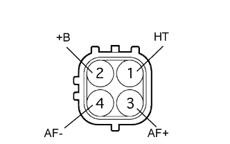 |
Disconnect the A18 A/F sensor connector.
Measure the resistance between the terminals of the A/F sensor connector.
| Tester Connection | Condition | Specified Condition |
| 1 (HT) -2 (+B) | 20°C (68°F) | 1.8 to 3.4 Ω |
| 1 (HT) -4 (AF-) | Always | 10 kΩ or higher |
|
| ||||
| OK | |
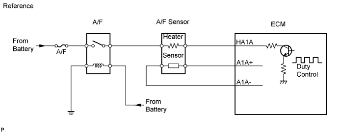
| 12.INSPECT RELAY (MARKING: A/F) |
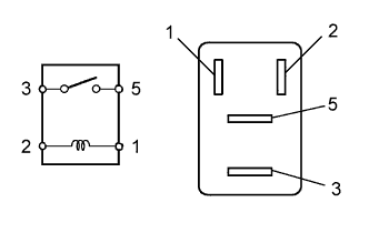 |
Remove the relay from the engine room relay block.
Check the resistance of the relay.
| Tester Connection | Specified Condition |
| 3 - 5 | 10 kΩ or higher |
| 3 - 5 | Below 1 Ω (when battery voltage is applied to terminals 1 and 2) |
|
| ||||
| OK | |
| 13.CHECK WIRE HARNESS (A/F SENSOR - ECM) |
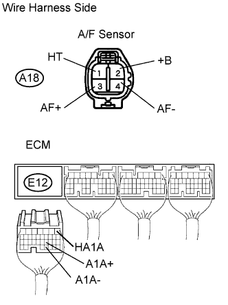 |
Disconnect the A18 sensor connector.
Disconnect the E12 ECM connector.
Measure the resistance of the wire harness side connectors.
| Tester Connection | Specified Condition |
| A18-1 (HT) - E12-1 (HA1A) | Below 1 Ω |
| A18-3 (AF+) - E12-21 (A1A+) | Below 1 Ω |
| A18-4 (AF-) - E12-31 (A1A-) | Below 1 Ω |
| A18-1 (HT) or E12-1 (HA1A) - Body ground | 10 kΩ or higher |
| A18-3 (AF+) or E12-21 (A1A+) - Body ground | 10 kΩ or higher |
| A18-4 (AF-) or E12-31 (A1A-) - Body ground | 10 kΩ or higher |
|
| ||||
| OK | |
| 14.REPLACE AIR FUEL RATIO SENSOR |
| NEXT | |
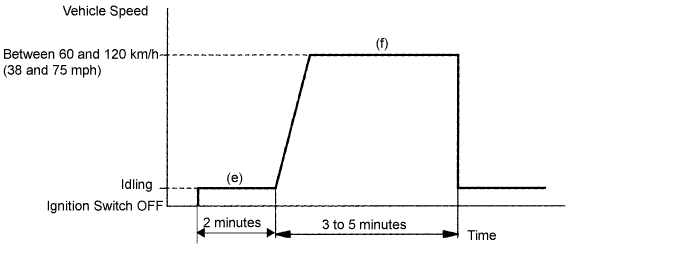
| 15.PERFORM CONFIRMATION DRIVING PATTERN |
| NEXT | |
| 16.CHECK IF DTC OUTPUT RECURS (DTC P0171 OR P0172) |
On the intelligent tester, select the following menu items: Powertrain / Engine and ECT / DTC.
Read DTCs.
| Display (DTC Output) | Proceed to |
| No output | A |
| P0171 or P0172 | B |
|
| ||||
| A | ||
| ||
