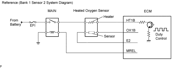
DTC P0136 Oxygen Sensor Circuit Malfunction (Bank 1 Sensor 2) |
DTC P0137 Oxygen Sensor Circuit Low Voltage (Bank 1 Sensor 2) |
DTC P0138 Oxygen Sensor Circuit High Voltage (Bank 1 Sensor 2) |
| DTC No. | DTC Detection Conditions | Trouble Areas |
| P0136 |
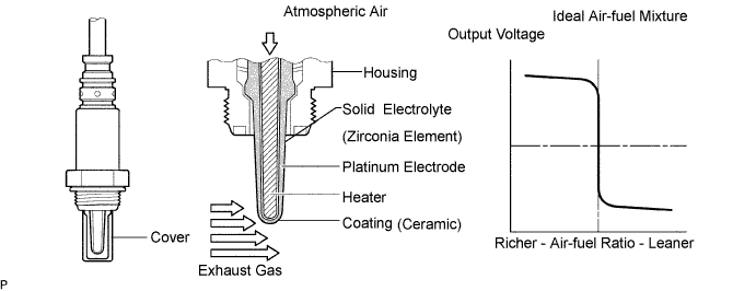
(a) Heated oxygen sensor voltage does not decrease to less than 0.2 V (b) Heated oxygen sensor voltage does not increase to more than 0.6 V
|
|
| P0137 |
(a) Heated oxygen sensor output voltage is less than 0.21 V (b) Target air-fuel ratio rich
|
|
| P0138 |
(a) heated oxygen sensor output voltage is 0.59 V or more (b) Target air-fuel ratio lean
|
|
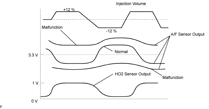
| Tester Display (Sensor) | Injection Volume | Status | Voltage |
| AFS B1 S1 (A/F) | + 25% | Rich | Less than 3.0 V |
| AFS B1 S1 (A/F) | - 12.5% | Lean | More than 3.35 V |
| O2S B1 S2 (HO2) | + 25% | Rich | More than 0.55 V |
| O2S B1 S2 (HO2) | - 12.5% | Lean | Less than 0.4 V |
| Case | A/F Sensor (Sensor 1) Output Voltage | HO2 Sensor (Sensor 2) Output Voltage | Main Suspected Trouble Areas | ||
| 1 | Injection Volume +25% -12.5% |  | Injection Volume +25% -12.5% | | - |
| Output Voltage More than 3.35 V Less than 3.0 V |  | Output Voltage More than 0.55 V Less than 0.4 V |  | ||
| 2 | Injection Volume +25% -12.5% | | Injection Volume +25% -12.5% | |
|
| Output Voltage Almost no reaction |  | Output Voltage More than 0.55 V Less than 0.4 V | | ||
| 3 | Injection Volume +25% -12.5% | | Injection Volume +25% -12.5% | |
|
| Output Voltage More than 3.35 V Less than 3.0 V | | Output Voltage Almost no reaction | | ||
| 4 | Injection volume +25% -12.5% | | Injection Volume +25% -12.5% | |
|
| Output Voltage Almost no reaction | | Output Voltage Almost no reaction | | ||
| 1.CHECK OTHER DTC OUTPUT |
Read the DTC using the intelligent tester.
| Display (DTC Output) | Proceed to |
| P0138 is output | A |
| P0137 is output | B |
| P0136 is output | C |
|
| ||||
|
| ||||
| A | |
| 2.READ VALUE OF DATA LIST |
Connect the intelligent tester to the DLC3.
Turn the ignition switch ON and turn the intelligent tester ON.
Enter the following menus: Powertrain / Engine and ECT / Data List / O2S B1 S2.
Run the engine at idle.
Read the output voltage of the heated oxygen sensor during idling.
| Heated Oxygen Sensor Output Voltage | Proceed to |
| More than 1.2 V | A |
| Less than 1.0 V | B |
|
| ||||
| A | |
| 3.CHECK WIRE HARNESS (CHECK FOR SHORT) |
 |
Turn the ignition switch OFF and wait for 5 minutes.
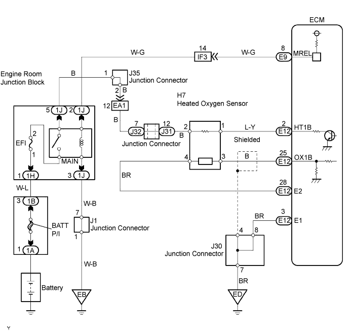
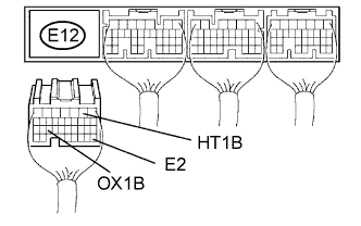
Disconnect the E12 ECM connector.
Measure the resistance of the wire harness side connectors.
| Tester Connection | Specified Condition |
| E12-2 (HT1B) - E12-25 (OX1B) | 10 kΩ or higher |
| E12-2 (HT1B) - E12-28 (E2) | 10 kΩ or higher |
|
| ||||
| NG | |
| 4.INSPECT HEATED OXYGEN SENSOR (CHECK FOR SHORT) |
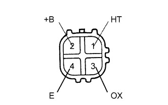 |
Disconnect the H7 sensor connector.
Measure the resistance of the sensor.
| Tester Connection | Specified Condition |
| 2 (+B) - 4 (E) | 10 kΩ or higher |
| 2 (+B) - 3 (OX) | 10 kΩ or higher |
|
| ||||
| NG | ||
| ||
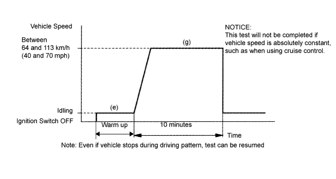
| 5.PERFORM CONFIRMATION DRIVING PATTERN |
| NEXT | |
| 6.READ OUTPUT DTC (CHECK MODE) |
Change the ECM to check mode with the intelligent tester. Enter the following menus: Powertrain / Engine and ECT / Check Mode.
Warm up the engine and drive the vehicle at over 40 km/h (25 mph) for an accumulated total of 10 minutes.
Read the DTC.
| Display (DTC output) | Proceed to |
| P0136 is output | A |
| No DTC | B |
|
| ||||
| A | ||
| ||
| 7.READ VALUE OF DATA LIST |
After warming up the engine, run the engine at 2,500 rpm for 3 minutes.
Read the output voltage of the heated oxygen sensor when the engine rpm is suddenly increased.
|
| ||||
| NG | |
| 8.CHECK FOR EXHAUST GAS LEAKAGE |
|
| ||||
| OK | |
| 9.INSPECT HEATED OXYGEN SENSOR (HEATER RESISTANCE) |
|
Disconnect the H7 sensor connector.
Measure the resistance of the sensor.
| Tester Connection | Condition | Specified Condition |
| 2 (+B) -1 (HT) | 20°C (68°F) | 11 to 16 Ω |
| 1 (HT) - 4 (E) | Always | 10 kΩ or higher |
|
| ||||
| OK | |
| 10.CHECK INTEGRATION RELAY (MAIN RELAY) |
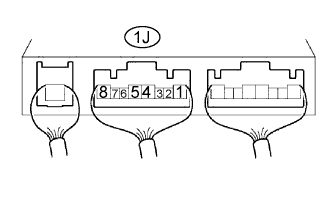 |
Remove the integration relay from the engine room junction block.
Measure the voltage of the MAIN relay.
| Tester Connection | Condition | Specified Condition |
| 1J-5 - Body ground | Ignition switch ON | 10 to 14 V |
|
| ||||
| OK | |
| 11.CHECK WIRE HARNESS (HEATED OXYGEN SENSOR - ECM) |
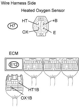 |
Disconnect the H7 heated oxygen sensor connector.
Disconnect the E12 ECM connector.
Measure the resistance of the wire harness side connectors.
| Tester Connection | Specified Condition |
| H7-1 (HT) - E11-2 (HT1B) H7-3 (OX) - E11-25 (OX1B) | Below 1 Ω |
| H7-1 (HT) - E11-2 (HT1B) - Body ground H7-3 (OX) - E11-25 (OX1B) - Body ground | 10 kΩ or higher |
|
| ||||
| OK | ||
| ||
| 12.PERFORM CONFIRMATION DRIVING PATTERN |
| NEXT | |
| 13.READ OUTPUT DTC (DTC P0136 IS OUTPUT AGAIN) |
Read DTC using the intelligent tester.
| Display (DTC Output) | Proceed to |
| P0136 is not output again | A |
| P0136 is output again | B |
|
| ||||
| B | |
| 14.REPLACE HEATED OXYGEN SENSOR |
| NEXT | |
| 15.PERFORM CONFIRMATION DRIVING PATTERN |
| NEXT | |
| 16.READ OUTPUT DTC (DTC P0136 IS OUTPUT AGAIN) |
Read DTC using the intelligent tester.
| Display (DTC Output) | Proceed to |
| P0136 is not output again | A |
| P0136 is output again | B |
|
| ||||
| B | |
| 17.PERFORM ACTIVE TEST (INJECTOR VOLUME) |
Start the engine and warm it up.
Connect the intelligent tester to the DLC3.
Turn ON the ignition switch and the intelligent tester main switch.
Enter the following menus: Powertrain / Engine and ECT / Active Test / Control the Injection Volume.
Using the intelligent tester, change the injection volume to check the A/F sensor output and heated oxygen sensor output values below.
| Tester Display (Sensor) | Voltage Variations | Proceed to |
| AFS B1 S1 (A/F) | Alternates between more and less than 3.3 V | OK |
| AFS B1 S1 (A/F) | Remains at more than 3.3 V | NG |
| AFS B1 S1 (A/F) | Remains at less than 3.3 V | NG |
|
| ||||
| NG | ||
| ||
