AUDIO AND VISUAL SYSTEM > Illumination Circuit |
| 1.CHECK WIRE HARNESS (RADIO RECEIVER ASSEMBLY - BATTERY AND BODY GROUND) |
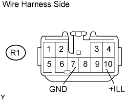 |
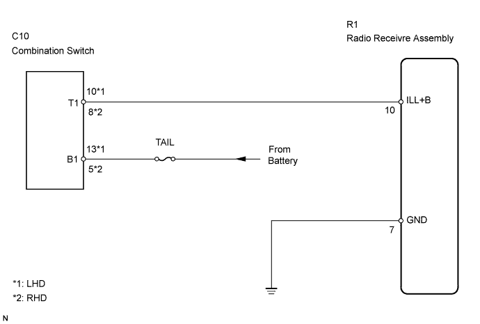
Disconnect the R1 receiver connector.
Measure the voltage and resistance of the wire harness side connector.
| Tester Connection | Condition | Specified Condition |
| R1-7 (GND) - Body ground | Always | Below 1 Ω |
| Tester Connection | Condition | Specified Condition |
| R1-10 (+ILL) - Body ground | Lamp control switch OFF | Below 1 V |
| R1-10 (+ILL) - Body ground | Light control switch TAIL or HEAD | 10 to 14 V |
|
| ||||
| OK | ||
| ||
