DTC    P2740    Transmission Fluid Temperature Sensor "B" Circuit

DTC    P2742    Transmission Fluid Temperature Sensor "B" Circuit Low Input

DTC    P2743    Transmission Fluid Temperature Sensor "B" Circuit High Input

for Preparation Click here


DESCRIPTION

The No. 2 ATF temperature sensor is on the transmission, just in front of the oil cooler inlet pipeline.
If the ECM detects an abnormally high ATF temperature near this sensor, it illuminates the warning light.

HINT:
  1. ATF temperature rises quickly when towing, climbing hills, in traffic, etc.
  2. If the No. 2 ATF temperature sensor becomes short-circuited, the signal that indicates the ATF temperature is 150°C (302°F) or higher is input in the ECM.

Vehicle conditions when the sensor is normal and when the sensor is short-circuited are indicated in the table below.

No. 2 ATF Temperature Sensor State
Detection Condition
Symptom
Recovery Condition
Sensor is normal
  1. ATF temperature more than 150°C (302°F)
  1. ATF temperature warning light remains ON
  1. ATF temperature less than 135°C (275°F)*2
  1. ATF temperature more than 130°C (266°F)
  1. Shift point too high
  1. ATF temperature less than 110°C (230°F)
  1. When the conditions (a) and (b) are satisfied
    1. ATF temperature more than 130°C (266°F)
    1. Engine coolant temperature more than 95°C (203°F)
  1. Lock-up at 3rd gear*1
  1. ATF temperature less than 110°C (230°F)*2 and engine coolant temperature more than 95°C (203°F)
Sensor is short-circuited
  1. Any conditions
  1. ATF temperature warning light remains ON
  2. Shift point too high
  1. Symptoms still occur
  1. Engine coolant temperature more than 95°C (203°F)
  1. Lock-up at 3rd gear*1
  1. Symptoms still occur

HINT:
*1: When ATF temperature is normal, transmission lock-up occurs in 5th gear with the shift lever on D, and 4th gear with the shift lever on 4.
*2: When ATF temperature is in the normal range, it decreases to less than 135°C (275°F) within 5 minutes with the shift lever on P or N in an idling state.


DTC No.
DTC Detection Condition
Trouble Area
P2740
  1. (a) and (b) are detected momentarily within 0.5 sec. when neither P2742 or P2743 are detected (1 trip detection logic):
    1. No. 2 ATF temperature sensor resistance is less than 25 Ω
    2. No. 2 ATF temperature sensor resistance is more than 156 kΩ

HINT:
Within 0.5 sec., the malfunction switches from (a) to (b) or from (b) to (a)

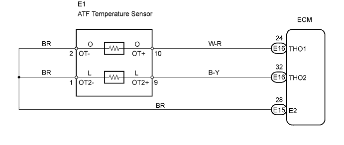
  1. Open or short in No. 2 ATF temperature sensor circuit
  2. No. 2 ATF temperature sensor
  3. ECM
P2742
No. 2 ATF temperature sensor resistance is less than 25 Ω for 0.5 sec. or more (1 trip detection logic)
  1. Short in No. 2 ATF temperature sensor circuit
  2. No. 2 ATF temperature sensor
  3. ECM
P2743
No. 2 ATF temperature sensor resistance is more than 156 kΩ when 15 minutes or more have passed after the engine start
DTC is detected for 0.5 sec. or more (1 trip detection logic)
  1. Open in No. 2 ATF temperature sensor circuit
  2. No. 2 ATF temperature sensor
  3. ECM

MONITOR DESCRIPTION

ATF temperature sensor converts ATF temperature to an electrical resistance value. Based on the resistance, the ECM determines the ATF temperature, and the ECM detects an open or short in the ATF temperature circuit. If the resistance value of the ATF temperature is less than 25 Ω*1 or more than 156 kΩ*2, the ECM interprets this as a fault in the ATF sensor or wiring. The ECM will illuminate the MIL and store the DTC.

HINT:
  1. *1: 150°C (302°F) or more is indicated regardless of the actual ATF temperature.
  2. *2: -40°C (-40°F) is indicated regardless of the actual ATF temperature.
  3. The ATF temperature can be checked on the intelligent tester display.


WIRING DIAGRAM


A110994E01


INSPECTION PROCEDURE

HINT:
Using the intelligent tester's Data List allows switch, sensor, actuator and other item values to be read without removing any parts. Reading the Data List early in troubleshooting is one way to save time.

  1. Warm up the engine.
  2. Turn the ignition switch OFF.
  3. Connect the intelligent tester to the DLC3.
  4. Turn the ignition switch ON and push the tester main switch ON.
  5. Enter the following menus: Powertrain / Engine and ECT / Data List.
  6. Follow the instructions on the tester and read the Data List.

Item
Measurement Item/
Range (Display)
Normal Condition
Diagnostic Note
A/T Temperature 2
No. 2 ATF temperature sensor value/
Min.: -40°C (-40°F)
Max.: 215°C (419°F)
  1. After stall test:
    Approximately 80°C (176°F)
  2. Equal to ambient temperature during cold soak
If value is -40°C (-40°F) or 215°C (419°F), No. 2 ATF temperature sensor circuit is opened or short circuited

CAUTION:
In the table above, the values listed under "Normal Condition" are reference values. Do not depend solely on these reference values when deciding whether a part is faulty or not.

HINT:
  1. When DTC P2742 is output and the intelligent tester output is 150°C (302°F) or more, there is a short circuit.
  2. When DTC P2743 is output and the intelligent tester output is -40°C (-40°F), there is an open circuit.
    Measure the resistance between terminal THO2 (OT2) and the body ground.


Temperature Displayed
Malfunction
-40°C (-40°F)
Open circuit
150°C (302°F) or more
Short circuit
1.INSPECT TRANSMISSION WIRE (ATF TEMPERATURE SENSOR)


    G020667E28
  1. Disconnect the E1 ATF temperature sensor connector.

  1. Measure the resistance of the temperature sensor.

    Standard resistance:
    Tester Connection
    Specified Condition
    1 (OT2-) - 9 (OT2+)
    25 Ω to 156 kΩ
    1 (OT2-) - Body ground
    10 kΩ or higher
    9 (OT2+) - Body ground
    10 kΩ or higher

    HINT:
    If the resistance is out of the specified range of either of the ATF temperatures shown in the table below, the driveability of the vehicle may decrease.

    Standard resistance:
    ATF Temperature
    Specified Condition
    20°C (68°F)
    3 to 4 kΩ
    110°C (230°F)
    0.22 to 0.28 kΩ


NG
REPAIR OR REPLACE TRANSMISSION WIRE
OK


2.CHECK WIRE HARNESS (TRANSMISSION WIRE - ECM)
G038618E01
  1. Disconnect the E15 and E16 ECM connectors.

  1. Measure the resistance of the wire harness side connectors.

    Standard resistance:
    Tester Connection
    Specified Condition
    E16-32 (THO2) - E15-28 (E2)
    25 Ω to 156 kΩ
    E16-32 (THO2) - Body ground
    10 kΩ or higher
    E15-28 (E2) - Body ground
    10 kΩ or higher


NG
REPAIR OR REPLACE HARNESS AND CONNECTOR
OK

REPLACE ECM