DTC U0001/A2 High Speed CAN Communication Bus |
| DTC No. | DTC Detection Condition | Trouble Area |
| U0001/A2 | No communication from TCM continues |
|
| 1.CHECK ECM (VC, +B VOLTAGE, E1 GROUND) |
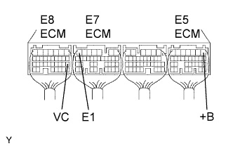 |
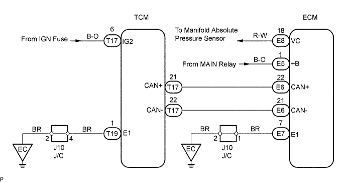
Measure the voltage and resistance of the ECM connectors.
| Tester Connection | Ignition Switch Position | Specified Condition |
| E5-1 (+B) - Body ground | ON | 9 to 14 V |
| E8-18 (VC) - Body ground | ON | 4.5 to 5.5 V |
| Tester Connection | Ignition Switch Position | Specified Condition |
| E7-7 (E1) - Body ground | - | 10 kΩ or higher |
|
| ||||
| OK | |
| 2.CHECK TCM (IG2 VOLTAGE, E1 GROUND) |
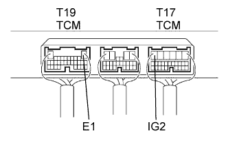 |
Measure the voltage and resistance of the TCM connectors.
| Tester Connection | Ignition Switch Position | Specified Condition |
| T17-6 (IG2) - Body ground | ON | 9 to 14 V |
| Tester Connection | Ignition Switch Position | Specified Condition |
| T19-1 (E1) - Body ground | - | 10 kΩ or higher |
|
| ||||
| OK | |
| 3.CHECK WIRE HARNESS (ECM - TCM) |
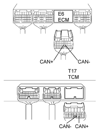 |
Disconnect the E6 ECM connector.
Disconnect the T17 TCM connector.
Measure the resistance of the wire harness side connectors.
| Tester Connection | Specified Condition |
| E6-22 (CAN+) - T17-21 (CAN+) | Below 1 Ω |
| E6-21 (CAN-) - T17-20 (CAN-) | Below 1 Ω |
| E6-22 (CAN+) or T17-21 (CAN+) - Body ground | 10 kΩ or higher |
| E6-21 (CAN-) or T17-20 (CAN-) - Body ground | 10 kΩ or higher |
|
| ||||
| OK | |
| 4.CHECK IF DTC OUTPUT RECURS |
Clear the DTC (Click here).
Replace the TCM.
Start the engine.
Read the DTCs (Click here).
| Display (DTC Output) | Proceed to |
| U0001/A2 | A |
| No DTC | B |
|
| ||||
| A | ||
| ||
