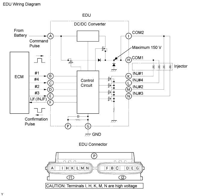
DTC P0200/97 Injector Circuit / Open |
| DTC No. | DTC Detection Condition | Trouble Area |
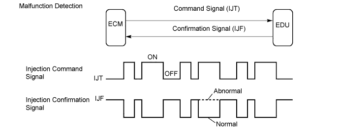
| P0200/97 | Open or short in EDU or injector circuit After engine is started, there is no IJF signal from EDU to ECM, despite ECM sending IJT signal to EDU (1 trip detection logic) |
|
| Required sensors | IJF signal from EDU |
| Frequency of operation | Continuous |
| Duration | 10 seconds |
| MIL operation | 1 driving cycle |
| Item | Specification Minimum | Specification Maximum |
| Engine speed | 500 rpm | - |
| Battery voltage | 11 V | - |
| Ignition switch | ON | ON |
| Threshold |
| The injection missing counter* for all the cylinders, or for one individual cylinder, reaches a specified number (taking approximately 1 second from starting the engine) *: Increments when no IJF signal is received from the EDU despite the ECM sending IJT signals |
| 1.INSPECT INJECTOR ASSEMBLY |
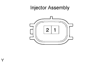 |
Disconnect the F5, F6, F7 and F8 injector connectors.
Measure the resistance of the injector.
| Tester Connection | Specified Condition |
| 1 - 2 | 0.85 to 1.05 Ω at 20°C (68°F) |
|
| ||||
| OK | |
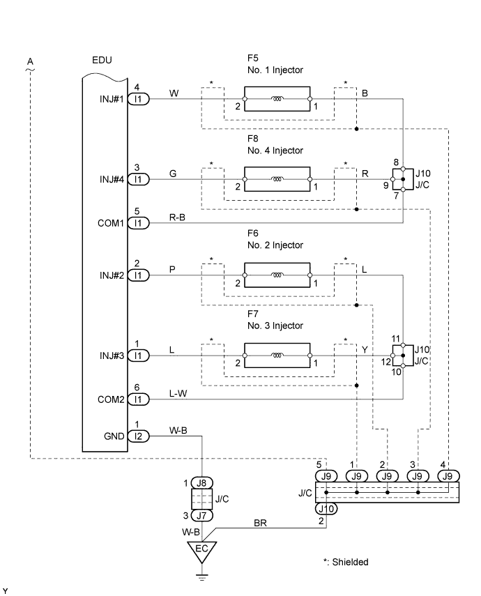
| 2.CHECK WIRE HARNESS (INJECTOR ASSEMBLY - EDU) |
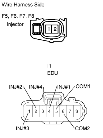 |
Check the wire harness between the injector and EDU (INJ terminal).
Disconnect the F5, F6, F7 and F8 connectors.
Disconnect the I1 EDU connector.
Measure the resistance of the wire harness side connectors.
| Tester Connection | Specified Condition |
| F5-2 - I1-4 (INJ#1) | Below 1 Ω |
| F6-2 - I1-2 (INJ#2) | Below 1 Ω |
| F7-2 - I1-1 (INJ#3) | Below 1 Ω |
| F8-2 - I1-3 (INJ#4) | Below 1 Ω |
| F5-1 - I1-5 (COM1) | Below 1 Ω |
| F6-1 - I1-6 (COM2) | Below 1 Ω |
| F7-1 - I1-6 (COM2) | Below 1 Ω |
| F8-1 - I1-5 (COM1) | Below 1 Ω |
| F5-2 or I1-4 (INJ#1) - Body ground | 10 kΩ or higher |
| F6-2 or I1-2 (INJ#2) - Body ground | 10 kΩ or higher |
| F7-2 or I1-1 (INJ#3) - Body ground | 10 kΩ or higher |
| F8-2 or I1-3 (INJ#4) - Body ground | 10 kΩ or higher |
| F5-1 or I1-5 (COM1) - Body ground | 10 kΩ or higher |
| F6-1 or I1-6 (COM2) - Body ground | 10 kΩ or higher |
| F7-1 or I1-6 (COM2) - Body ground | 10 kΩ or higher |
| F8-1 or I1-5 (COM1) - Body ground | 10 kΩ or higher |
|
| ||||
| OK | |
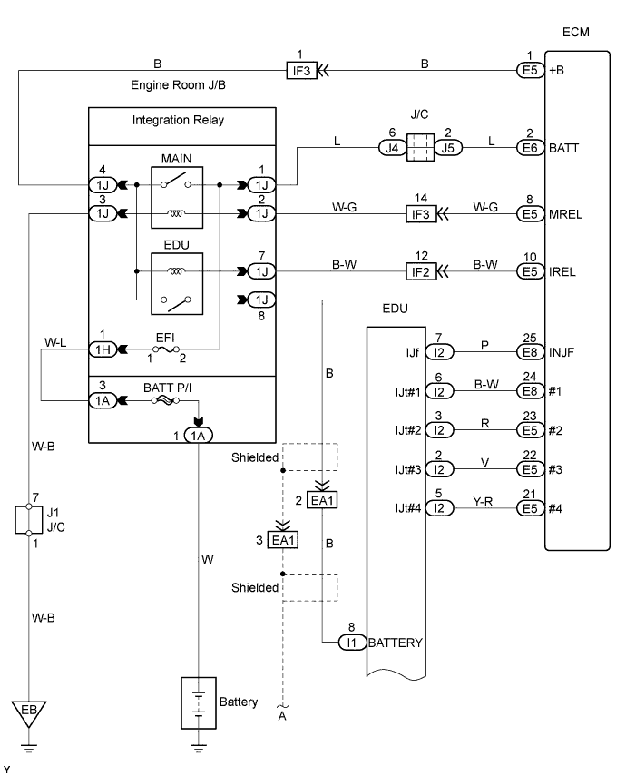
| 3.CHECK WIRE HARNESS (EDU - ECM) |
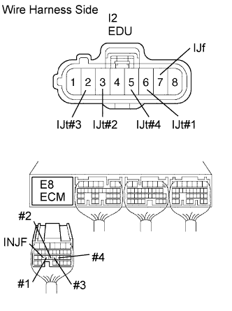 |
Disconnect the I2 EDU connector.
Disconnect the E8 ECM connector.
Measure the resistance of the wire harness side connectors.
| Tester Connection | Specified Condition |
| I2-6 (IJt#1) - E8-24 (#1) | Below 1 Ω |
| I2-3 (IJt#2) - E8-23 (#2) | Below 1 Ω |
| I2-2 (IJt#3) - E8-22 (#3) | Below 1 Ω |
| I2-5 (IJt#4) - E8-21 (#4) | Below 1 Ω |
| I2-7 (IJf) - E8-25 (INJF) | Below 1 Ω |
| I2-6 (IJt#1) or E8-24 (#1) - Body ground | 10 kΩ or higher |
| I2-3 (IJt#2) or E8-23 (#2) - Body ground | 10 kΩ or higher |
| I2-2 (IJt#3) or E8-22 (#3) - Body ground | 10 kΩ or higher |
| I2-5 (IJt#4) or E8-21 (#4) - Body ground | 10 kΩ or higher |
| I2-7 (IJf) or E8-25 (INJF) - Body ground | 10 kΩ or higher |
|
| ||||
| OK | |
| 4.CHECK INJECTOR DRIVER (BATTERY VOLTAGE) |
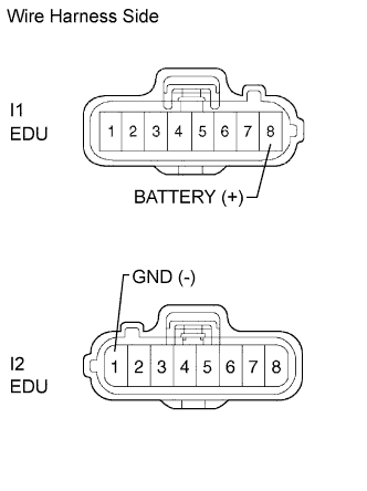 |
Disconnect the I1 and I2 EDU connectors.
Turn the ignition switch ON.
Measure the voltage of the wire harness side connectors.
| Tester Connection | Specified Condition |
| I1-8 (BATTERY) - I2-1 (GND) | 9 to 14 V |
|
| ||||
| OK | |
| 5.CHECK ECM (INJECTOR VOLTAGE) |
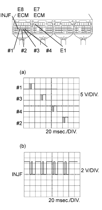 |
While idling the engine, check the waveform of the ECM connectors using an oscilloscope.
| Tester Connection | Specified Condition |
| E8-24 (#1) - E7-7 (E1) | Correct waveform is shown |
| E8-23 (#2) - E7-7 (E1) | Correct waveform is shown |
| E8-22 (#3) - E7-7 (E1) | Correct waveform is shown |
| E8-21 (#4) - E7-7 (E1) | Correct waveform is shown |
| E8-25 (INJF) - E7-7 (E1) | Correct waveform is shown |
| Tool Setting | Condition |
| (a) 5 V/DIV., 20 msec./DIV. (b) 2 V/DIV., 20 msec./DIV. | Idling with warm engine |
|
| ||||
| OK | |
| 6.REPLACE INJECTOR DRIVER |
| NEXT | ||
| ||
