DTC    P0180/39    Fuel Temperature Sensor "A" Circuit

DTC    P0182/39    Fuel Temperature Sensor "A" Circuit Low Input

DTC    P0183/39    Fuel Temperature Sensor "A" Circuit High Input

for Preparation Click here


DESCRIPTION

G036559E03
The fuel temperature sensor monitors the fuel temperature. The fuel temperature sensor has a thermistor that varies its resistance depending on the fuel temperature. When the fuel temperature is low, the resistance in the thermistor increases. When the temperature is high, the resistance decreases. The variations in resistance are communicated to the ECM as changes in voltage (see Fig. 1).
The fuel temperature sensor is connected to the ECM. The 5 V power source voltage in the ECM is applied to the fuel temperature sensor from terminal THF via resistor R.
The resistor R and fuel temperature sensor are connected in series. When the resistance value of the fuel temperature sensor changes in accordance with changes in the fuel temperature, and the voltage at terminal THF also changes. Based on this signal, the ECM corrects the pressure control compensation of the supply pump and errors.

DTC No.
DTC Detection Condition
Trouble Area
P0180/39
Open or short in fuel temperature sensor circuit for 0.5 seconds
(1 trip detection logic)
  1. Open or short in fuel temperature sensor circuit
  2. Fuel temperature sensor
  3. ECM
P0182/39
Short in fuel temperature sensor circuit for 0.5 seconds
(1 trip detection logic)
  1. Open or short in fuel temperature sensor circuit
  2. Fuel temperature sensor
  3. ECM
P0183/39
Open in fuel temperature sensor circuit for 0.5 seconds
(1 trip detection logic)
  1. Open or short in fuel temperature sensor circuit
  2. Fuel temperature sensor
  3. ECM

HINT:
When DTC P0180/39, P0182/39 and/or P0183/39 is detected, check the fuel temperature by entering the following menus on the intelligent tester: Powertrain / Engine / Data List / Fuel Temperature.

Temperature Displayed
Malfunction
-40°C (-40°F)
Open circuit
140°C (284°F) or more
Short circuit


WIRING DIAGRAM


A099774E02


INSPECTION PROCEDURE

HINT:
  1. If DTCs related to different systems that have terminal E2 as the ground terminal are output simultaneously, terminal E2 may have an open circuit.
  2. Read freeze frame data using the intelligent tester. Freeze frame data records the engine conditions when a malfunction is detected. When troubleshooting, freeze frame data can help determine if the vehicle was running or stopped, if the engine was warmed up or not, and other data from the time the malfunction occurred.

NOTICE:
If the ECM is replaced, the new ECM needs initialization (Click here).

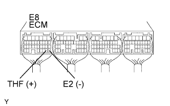
1.CHECK ECM (THF VOLTAGE)
A066060E35
  1. Start the engine.

  1. Measure the voltage of the ECM connector.

    Standard voltage:
    Tester Connection
    Condition
    Specified Condition
    E8-29 (THF) - E8-28 (E2)
    Idling, intake air temperature at 20°C (68°F)
    0.5 to 3.4 V


OK
CHECK FOR INTERMITTENT PROBLEMS
NG


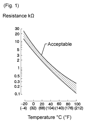
2.INSPECT FUEL TEMPERATURE SENSOR
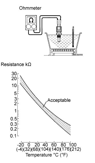
A111100E01
  1. Remove the sensor.

  1. Measure the resistance of the sensor.

    Standard resistance:
    Condition
    Specified Condition
    Approximately 20°C (68°F)
    2.32 to 2.59 kΩ
    Approximately 80°C (176°F)
    0.310 to 0.326 kΩ

    NOTICE:
    When checking the fuel temperature sensor in water, keep the terminals dry. After the check, wipe the sensor dry.


NG
REPLACE FUEL TEMPERATURE SENSOR
OK


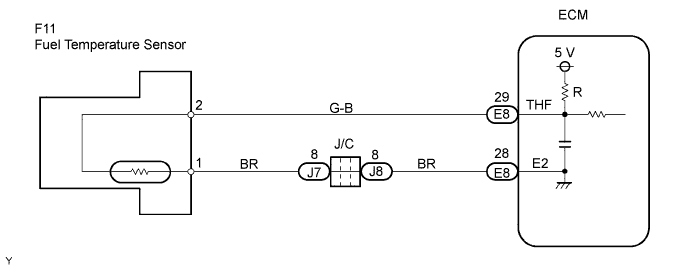
3.CHECK WIRE HARNESS (ECM - FUEL TEMPERATURE SENSOR)
G035034E02
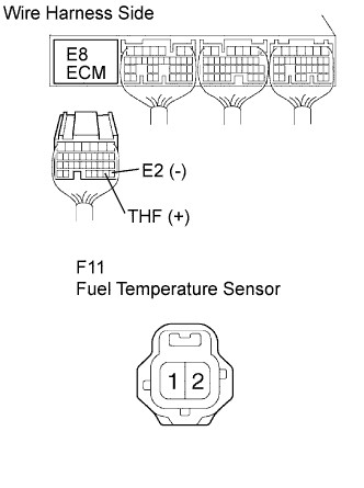
  1. Disconnect the E8 ECM connector.

  1. Disconnect the F11 sensor connector.

  1. Measure the resistance of the wire harness side connectors.

    Standard resistance:
    Tester Connection
    Specified Condition
    E8-29 (THF) - F11-2 (THF)
    Below 1 Ω
    E8-28 (E2) - F11-1 (E2)
    Below 1 Ω
    E8-29 (THF) or F11-2 (THF) -
    Body ground
    10 kΩ or higher
    E8-28 (E2) or F11-1 (E2) -
    Body ground
    10 kΩ or higher


NG
REPAIR OR REPLACE HARNESS AND CONNECTOR
OK

REPLACE ECM