DTC P0088/78 Fuel Rail / System Pressure - Too High |
DTC P1229/78 Fuel Pump System |
| DTC No. | DTC Detection Condition | Trouble Area |
| P0088/78 | Internal fuel pressure of common rail is too high: Fuel pressure exceeds 200 MPa (2,039 kgf/cm 2, 29,007 psi) (1 trip detection logic) |
|
| P1229/78 | Fuel over-feed: Internal fuel pressure continues exceeding target fuel pressure despite ECM closing suction control valve (1 trip detection logic) |
|
| Engine Speed | Fuel Pressure |
| Idling | Approximately 25 to 35 MPa |
| 3,000 rpm (No engine load) | Approximately 35 to 55 MPa |
| Required sensors | Fuel pressure sensor |
| Frequency of operation | Continuous |
| Duration | 1 second |
| MIL operation | 1 driving cycle |
| Required sensors | Fuel pressure sensor |
| Frequency of operation | Continuous |
| Duration | 1 minute |
| MIL operation | 1 driving cycle |
| Specification |
| The monitor will not run if the fuel pressure sensor or suction control valve circuit is malfunctioning |
| Item | Specification |
| Target fuel pressure variation | Small |
| The monitor will not run if the fuel pressure sensor or suction control valve circuit is malfunctioning | |
| Detection Criteria | Threshold |
| Fuel pressure sensor | 200 MPa (2,039 kgf/cm2, 29,007 psi) or more |
| Detection Criteria | Threshold |
| The internal fuel pressure of the common rail when the suction control valve is closed | Remains higher than target fuel pressure |
| 1.CHECK OTHER DTC OUTPUT (IN ADDITION TO DTC P0088/78 AND/OR P1229/78) |
Connect the intelligent tester to the DLC3.
Turn the ignition switch ON and turn the intelligent tester ON.
Enter the following menus: Powertrain / Engine / DTC.
Read the DTCs.
| Display (DTC Output) | Proceed to |
| P0088/78, or P0088/78 and P1229/78 | A |
| P1229/78 | B |
| P0190/49, P0192/49 and/or P0193/49 | C |
|
| ||||
|
| ||||
| A | |
| 2.REPLACE COMMON RAIL ASSEMBLY (PRESSURE LIMITER) |
| NEXT | |
| 3.INSPECT SUPPLY PUMP ASSEMBLY (SUCTION CONTROL VALVE) |
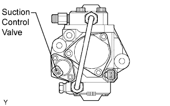 |
Disconnect the S8 valve connector.
Measure the resistance of the suction control valve.
|
| ||||
| OK | |
| 4.CHECK IF DTC OUTPUT RECURS (DTC P1229/78) |
Connect the intelligent tester to the DLC3.
Turn the ignition switch ON and turn the intelligent tester ON.
Enter the following menus: Powertrain / Engine / DTC / Clear.
Clear the DTC(s).
Disconnect the suction control valve connector and then start the engine. Wait for 1 minute.
Enter the following menus: Powertrain / Engine / DTC.
Read the DTCs.
| Display (DTC Output) | Proceed to |
| No output | A |
| P1229/78 | B |
|
| ||||
| A | |
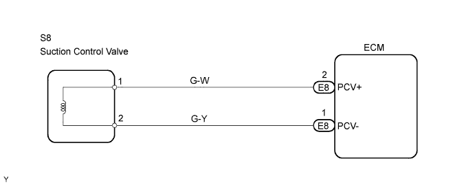
| 5.CHECK WIRE HARNESS (SUCTION CONTROL VALVE - ECM) |
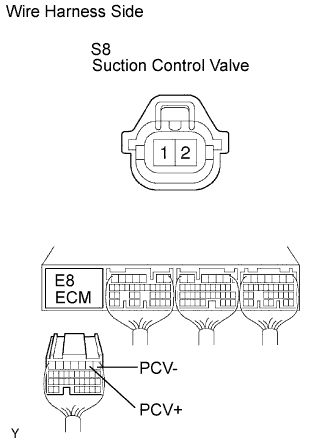 |
Disconnect the S8 valve connector.
Disconnect the E8 ECM connector.
Measure the resistance of the wire harness side connectors.
| Tester Connection | Specified Condition |
| S8-1 (PCV+) - E8-2 (PCV+) | Below 1 Ω |
| S8-2 (PCV-) - E8-1 (PCV-) | Below 1 Ω |
| S8-1 (PCV+) or E8-2 (PCV+) - Body ground | 10 kΩ higher |
| S8-2 (PCV-) or E8-1 (PCV-) - Body ground | 10 kΩ higher |
|
| ||||
| OK | |
| 6.CHECK ECM (PCV SIGNAL) |
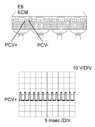 |
While cranking or idling the engine, check the waveform of the ECM connector using an oscilloscope.
| Tester Connection | Specified Condition |
| E8-2 (PCV+) - E8-1 (PCV-) | Correct waveform shown |
| Tool Setting | Condition |
| 10 V/DIV., 5 msec./DIV. | Idling or cranking with warm engine |
|
| ||||
| OK | ||
| ||
