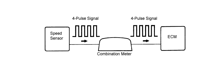
DTC P0500/42 Vehicle Speed Sensor "A" |
| DTC No. | DTC Detection Condition | Trouble Area |
| P0500/42 | Conditions (a), (b) and (c) continue for 7 seconds or more: (1 trip detection logic) (a) Engine coolant temperature is more than 70°C (158°F) (b) Engine speed is between 2,650 rpm and 3,500 rpm (c) No speed signal is input to ECM |
|
| 1.CHECK OPERATION OF SPEEDOMETER |
Check the speedometer reading in the combination meter.
|
| ||||
| OK | |
| 2.READ DATA LIST (VEHICLE SPEED) |
Connect the intelligent tester to the DLC3.
Start the engine and turn the intelligent tester ON.
Enter the following menus: Powertrain / Engine / Data List / Vehicle Speed.
While the vehicle is running, check the vehicle speed at an engine speed of 2,000 rpm or more.
|
| ||||
| NO | |
| 3.CHECK ECM (SPD SIGNAL) |
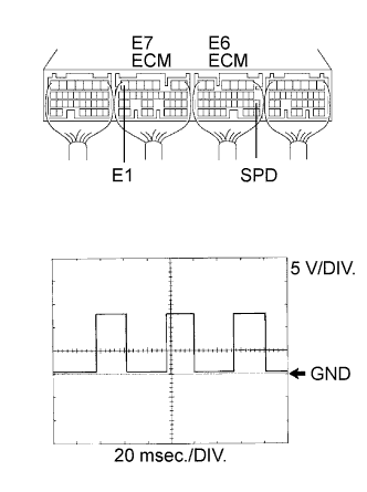 |
While idling the engine, check the waveform of the ECM connectors using an oscilloscope.
Move the shift lever to N.
Jack up the vehicle.
Turn the ignition switch ON.
Measure the voltage of the ECM connectors as the wheel is turned slowly.
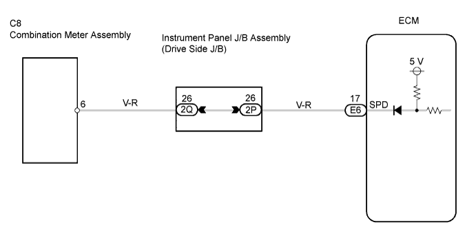
| Tester Connection | Specified Condition |
| E6-17 (SPD) - E7-7 (E1) | Correct waveform is shown |
| Tool Setting | Condition |
| 5 V/DIV., 20 msec./DIV. | Turn the rear wheel slowly |
|
| ||||
| OK | ||
| ||
| 1.CHECK OPERATION OF SPEEDOMETER |
Check the speedometer reading in the combination meter.
|
| ||||
| OK | |
| 2.CHECK ECM (SPD SIGNAL) |
|
While idling the engine, check the waveform of the ECM connectors using an oscilloscope.
Move the shift lever to N.
Jack up the vehicle.
Turn the ignition switch ON.
Measure the voltage of the ECM connectors as the wheel is turned slowly.
| Tester Connection | Specified Condition |
| E6-17 (SPD) - E7-7 (E1) | Correct waveform is shown |
| Tool Setting | Condition |
| 5 V/DIV., 20 msec./DIV. | Turn the rear wheel slowly |
|
| ||||
| OK | ||
| ||
