DTC P0335/12 Crankshaft Position Sensor "A" Circuit |
DTC P0339/13 Crankshaft Position Sensor "A" Circuit Intermittent |
| DTC No. | DTC Detection Condition | Trouble Area |
| P0335/12 |
|
|
| P0339/13 | No crankshaft position sensor signal to ECM is input for 0.05 seconds or more, and conditions 1, 2 and 3 are met (1 trip detection logic):
|
|
| 1.INSPECT CRANKSHAFT POSITION SENSOR (RESISTANCE) |
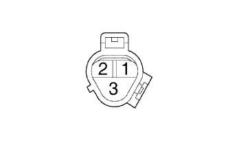 |
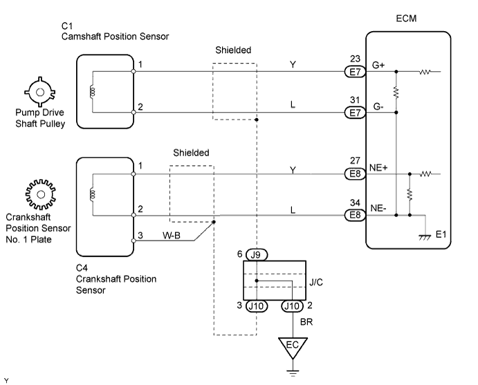
Disconnect the C4 sensor connector.
 |
Measure the resistance of the sensor.
| Tester Connection | Condition | Specified Condition |
| 1 - 2 | Cold | 1,630 to 2,740 Ω |
| 1 - 2 | Hot | 2,065 to 3,225 Ω |
| Tester Connection | Specified Condition |
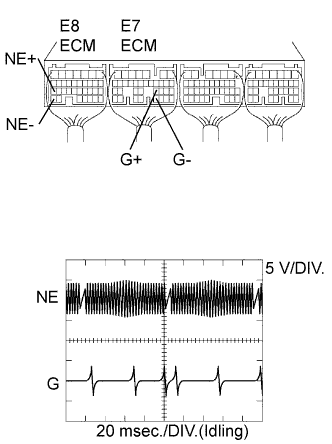
| E7-23 (G+) - E7-31 (G-) E8-27 (NE+) - E8-34 (NE-) | Correct waveform is as shown |
| Tool Setting | Condition |
| 5 V/DIV., 20 msec./DIV. | Idling with warm engine |
|
| ||||
| OK | |
| 2.CHECK WIRE HARNESS (CRANKSHAFT POSITION SENSOR - ECM) |
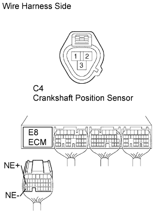 |
Disconnect the C4 sensor connector.
Disconnect the E8 ECM connector.
Measure the resistance of the wire harness side connectors.
| Tester Connection | Specified Condition |
| C4-1 - E8-27 (NE+) | Below 1 Ω |
| C4-2 - E8-34 (NE-) | Below 1 Ω |
| C4-1 or E8-27 (NE+) - Body ground | 10 kΩ or higher |
| C4-2 or E8-34 (NE-) - Body ground | 10 kΩ or higher |
|
| ||||
| OK | |
| 3.CHECK SENSOR INSTALLATION (CRANKSHAFT POSITION SENSOR) |
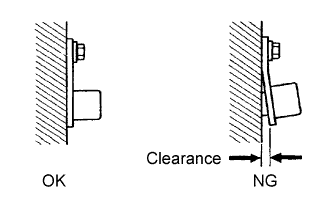 |
Check the sensor installation.
|
| ||||
| OK | |
| 4.CHECK CRANKSHAFT POSITION SENSOR NO. 1 PLATE |
Check the teeth of the crankshaft position sensor No. 1 plate.
|
| ||||
| OK | ||
| ||
