DTC P0504/51 Brake Switch "A" / "B" Correlation |
| Signal | Brake Pedal Released | In Transition | Brake Pedal Depressed |
| STP | OFF | ON | ON |
| ST1- | ON | ON | OFF |
| DTC No. | DTC Detection Condition | Trouble Area |
| P0504/51 | Conditions (1), (2) and (3) continue for 0.5 seconds or more:
|
|
| 1.CHECK STOP LIGHT (OPERATION) |
Check if the stop lights turn ON and OFF normally when the brake pedal is depressed and released.
|
| ||||
| OK | |
| 2.READ DATA LIST (STP SIGNAL, ST1 - VOLTAGE) |
 |
Connect the intelligent tester to the DLC3.
Turn the ignition switch ON and turn the intelligent tester ON.
Enter the following menus: Powertrain / Engine / Data List / Stop Light Switch.
Check the result.
| Brake Pedal | Specified Condition |
| Depressed | STP signal ON |
| Released | STP signal OFF |
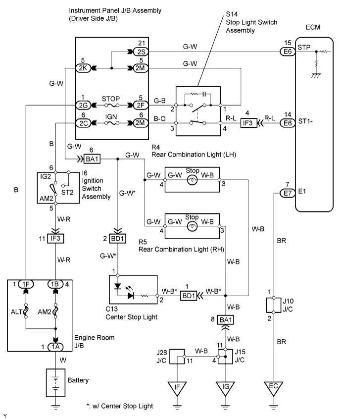
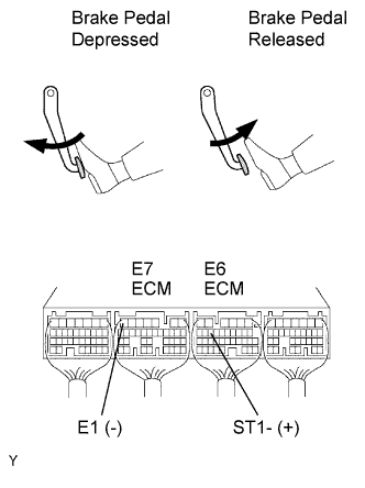
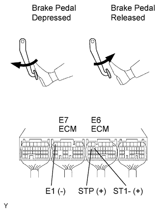
Measure the voltage of the ECM connectors.
| Tester Connection | Brake Pedal | Specified Condition |
| E6-14 (ST1-) - E7-7 (E1) | Depressed | Below 1.5 V |
| E6-14 (ST1-) - E7-7 (E1) | Released | 7.5 to 14 V |
|
| ||||
| NG | |
| 3.INSPECT STOP LIGHT SWITCH ASSEMBLY |
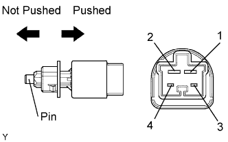 |
Remove the stop light switch.
Measure the resistance of the switch.
| Tester Connection | Switch Condition | Specified Condition |
| 1 - 2 | Pin not pushed | Below 1 Ω |
| 3 - 4 | Pin not pushed | 10 kΩ or higher |
| 1 - 2 | Pin pushed | 10 kΩ or higher |
| 3 - 4 | Pin pushed | Below 1 Ω |
|
| ||||
| OK | |
| 4.CHECK WIRE HARNESS (STOP LIGHT SWITCH - ECM) |
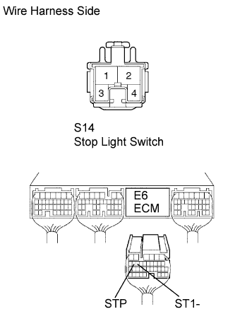 |
Disconnect the S14 stop light switch connector.
Disconnect the E6 ECM connector.
Measure the resistance of the wire harness side connector.
| Tester Connection | Specified Condition |
| S14-1 - E6-15 (STP) | Below 1 Ω |
| S14-4 - E6-14 (ST1-) | Below 1 Ω |
| S14-1 or E6-15 (STP) - Body ground | 10 kΩ or higher |
| S14-4 or E6-14 (ST1-) - Body ground | 10 kΩ or higher |
|
| ||||
| OK | ||
| ||
| 1.CHECK STOP LIGHT (OPERATION) |
Check if the stop lights turn ON and OFF normally when the brake pedal is depressed and released.
|
| ||||
| OK | |
| 2.CHECK ECM (STP, ST1- VOLTAGE) |
 |
Turn the ignition switch ON.
Measure the voltage of the ECM connectors.
| Tester Connection | Brake Pedal Condition | Specified Condition |
| E6-15 (STP) - E7-7 (E1) | Depressed | 7.5 to 14 V |
| E6-15 (STP) - E7-7 (E1) | Released | Below 1.5 V |
| E6-14 (ST1-) - E7-7 (E1) | Depressed | Below 1.5 V |
| E6-14 (ST1-) - E7-7 (E1) | Released | 7.5 to 14 V |
|
| ||||
| NG | |
| 3.INSPECT STOP LIGHT SWITCH ASSEMBLY |
|
Remove the stop light switch.
Measure the resistance of the switch.
| Tester Connection | Switch Condition | Specified Condition |
| 1 - 2 | Pin not pushed | Below 1 Ω |
| 3 - 4 | Pin not pushed | 10 kΩ or higher |
| 1 - 2 | Pin pushed | 10 kΩ or higher |
| 3 - 4 | Pin pushed | Below 1 Ω |
|
| ||||
| OK | |
| 4.CHECK WIRE HARNESS (STOP LIGHT SWITCH - ECM) |
|
Disconnect the S14 switch connector.
Disconnect the E6 ECM connector.
Measure the resistance of the wire harness side connector.
| Tester Connection | Specified Condition |
| S14-1 - E6-15 (STP) | Below 1 Ω |
| S14-4 - E6-14 (ST1-) | Below 1 Ω |
| S14-1 or E6-15 (STP) - Body ground | 10 kΩ or higher |
| S14-4 or E6-14 (ST1-) - Body ground | 10 kΩ or higher |
|
| ||||
| OK | ||
| ||
