DTC P2121/19 Throttle / Pedal Position Sensor / Switch "D" Circuit Range / Performance |
| DTC No. | DTC Detection Condition | Trouble Area |
| P2121/19 | Condition 1 continues for 2 seconds:
|
|
| 1.READ DATA LIST (ACCEL POSITION 1, ACCEL POSITION 2) |
 |
Connect the intelligent tester to the DLC3.
Turn the ignition switch ON and turn the intelligent tester ON.
Enter the following menus: Powertrain / Engine / Data List / Accel Position 1 and Accel Position 2.
Read the values.
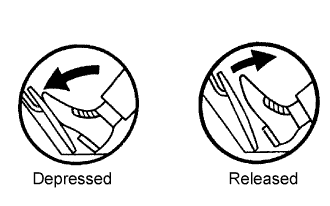
| Accelerator Pedal | Accel Position 1 | Accel Position 2 |
| Released | 0.6 to 1.0 V | 1.4 to 1.8 V |
| Depressed | 2.9 to 4.2 V | 3.7 to 5.0 V |
|
| ||||
| NG | |
| 2.CHECK WIRE HARNESS (ACCELERATOR PEDAL POSITION SENSOR - ECM) |
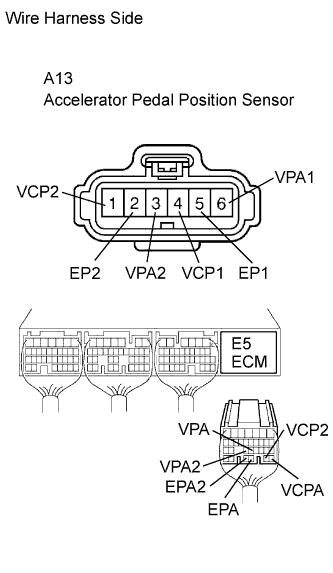 |
Disconnect the A13 sensor connector.
Disconnect the E5 ECM connector.
Measure the resistance of the wire harness side connectors.
| Tester Connection | Specified Condition |
| A17-1 (VCP2) - E5-27 (VCP2) A17-2 (EP2) - E5-29 (EPA2) A17-3 (VPA2) - E5-23 (VPA2) A17-4 (VCP1) - E5-26 (VCPA) A17-5 (EP1) - E5-28 (EPA) A17-6 (VPA1) - E5-22 (VPA) | Below 1 Ω |
| A17-1 (VCP2) or E5-27 (VCP2) - Body ground A17-2 (EP2) or E5-29 (EPA2) - Body ground A17-3 (VPA2) or E5-23 (VPA2) - Body ground A17-4 (VCP1) or E5-26 (VCPA) - Body ground A17-5 (EP1) or E5-28 (EPA) - Body ground A17-6 (VPA1) or E5-22 (VPA) - Body ground | 10 kΩ or higher |
|
| ||||
| OK | ||
| ||
| 1.INSPECT ECM (VPA, VPA2 VOLTAGE) |
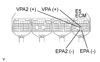 |
Turn the ignition switch ON.
Measure the voltage of the ECM connector.
| Tester Connection | Accelerator Pedal Condition | Specified Condition |
| E5-22 (VPA) - E5-28 (EPA) | Released | 0.6 to 1.0 V |
| E5-22 (VPA) - E5-28 (EPA) | Depressed | 2.9 to 4.2 V |
| E5-23 (VPA2) - E5-29 (EPA2) | Released | 1.4 to 1.8 V |
| E5-23 (VPA2) - E5-29 (EPA2) | Depressed | 3.7 to 5.0 V |
|
| ||||
| NG | |
| 2.CHECK WIRE HARNESS (ACCELERATOR PEDAL POSITION SENSOR - ECM) |
|
Disconnect the A13 sensor connector.
Disconnect the E5 ECM connector.
Measure the resistance of the wire harness side connectors.
| Tester Connection | Specified Condition |
| A17-1 (VCP2) - E5-27 (VCP2) A17-2 (EP2) - E5-29 (EPA2) A17-3 (VPA2) - E5-23 (VPA2) A17-4 (VCP1) - E5-26 (VCPA) A17-5 (EP1) - E5-28 (EPA) A17-6 (VPA1) - E5-22 (VPA) | Below 1 Ω |
| A17-1 (VCP2) or E5-27 (VCP2) - Body ground A17-2 (EP2) or E5-29 (EPA2) - Body ground A17-3 (VPA2) or E5-23 (VPA2) - Body ground A17-4 (VCP1) or E5-26 (VCPA) - Body ground A17-5 (EP1) or E5-28 (EPA) - Body ground A17-6 (VPA1) or E5-22 (VPA) - Body ground | 10 kΩ or higher |
|
| ||||
| OK | ||
| ||
