DTC P0115/22 Engine Coolant Temperature Circuit |
DTC P0117/22 Engine Coolant Temperature Circuit Low Input |
DTC P0118/22 Engine Coolant Temperature Circuit High Input |
| DTC No. | DTC Detection Condition | Trouble Area |
| P0115/22 | Open or short in ECT sensor circuit for 0.5 seconds (1 trip detection logic) |
|
| P0117/22 | Short in ECT sensor circuit for 0.5 seconds (sensor resistance value less than 79 Ω) | |
| P0118/22 | Open in ECT sensor circuit for 0.5 seconds (sensor resistance value more than 156 kΩ) (1 trip detection logic) |
| Temperature Displayed | Malfunction |
| -40°C (-40°F) | Open circuit |
| 140°C (284°F) or more | Short circuit |
| 1.READ DATA LIST (ENGINE COOLANT TEMPERATURE) |
Connect the intelligent tester to the DLC3.
Turn the ignition switch ON and turn the intelligent tester ON.
Enter the following menus: Powertrain / Engine / Data List / Coolant Temp.
Read the values.
| Temperature Displayed | Proceed to |
| -40°C (-40°F) | A |
| 140°C (284°F) or more | B |
| OK (Same as actual engine coolant temperature) | C |
|
| ||||
|
| ||||
| A | |
| 2.READ DATA LIST (CHECK FOR OPEN IN WIRE HARNESS) |
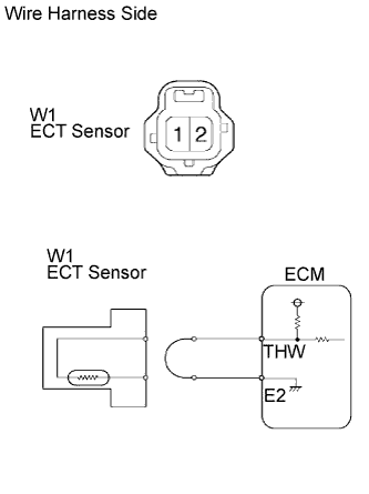 |
Disconnect the W1 ECT sensor connector.
Connect terminals 1 and 2 of the ECT sensor wire harness side connector.
Connect the intelligent tester to the DLC3.
Turn the ignition switch ON and turn the intelligent tester ON.
Enter the following menus: Powertrain / Engine / Data List / Coolant Temp.
Read the values.
|
| ||||
| NG | |
| 3.READ DATA LIST (CHECK FOR OPEN IN ECM) |
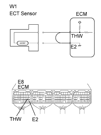 |
Disconnect the W1 ECT sensor connector.
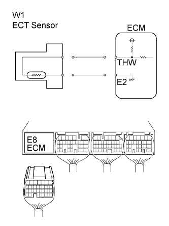
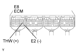
Connect terminals THW and E2 of the E8 ECM connector.
Connect the intelligent tester to the DLC3.
Turn the ignition switch ON and turn the intelligent tester ON.
Enter the following menus: Powertrain / Engine / Data List / Coolant Temp.
Read the values.
|
| ||||
| NG | ||
| ||
| 4.READ DATA LIST (CHECK FOR SHORT IN WIRE HARNESS) |
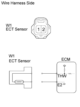 |
Disconnect the W1 ECT sensor connector.
Connect the intelligent tester to the DLC3.
Turn the ignition switch ON and turn the intelligent tester ON.
Enter the following menus: Powertrain / Engine / Data List / Coolant Temp.
Read the values.
|
| ||||
| NG | |
| 5.READ DATA LIST (CHECK FOR SHORT IN ECM) |
 |
Disconnect the W1 ECT sensor connector.
Disconnect the E8 ECM connector.
Connect the intelligent tester to the DLC3.
Turn the ignition switch ON and turn the intelligent tester ON.
Enter the following menus: Powertrain / Engine / Data List / Coolant Temp.
Read the values.
|
| ||||
| NG | ||
| ||
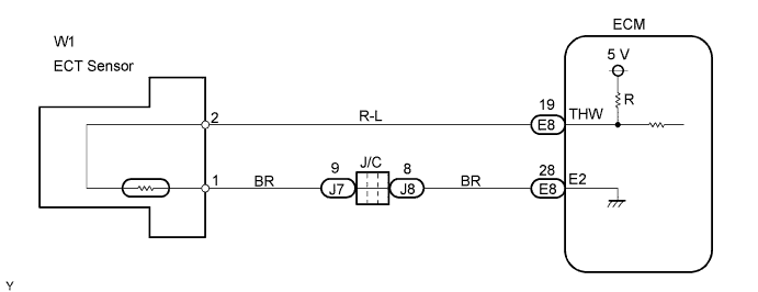
| 1.CHECK ECM (THW VOLTAGE) |
 |
Start the engine.
Measure the voltage of the ECM connector.
| Tester Connection | Condition | Specified Condition |
| E8-19 (THW) - E8-28 (E2) | Idling, Engine coolant temperature between 60 and 120°C (140 and 248°F) | 0.2 to 1.0 V |
|
| ||||
| NG | |
| 2.INSPECT ENGINE COOLANT TEMPERATURE SENSOR |
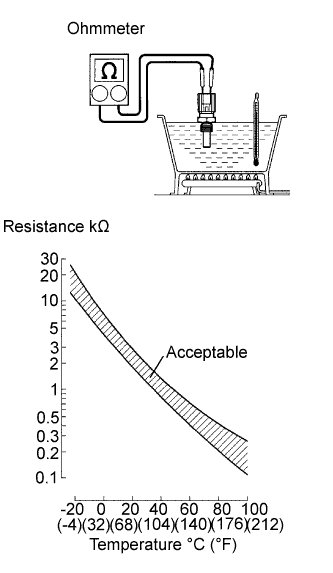 |
Remove the sensor.
Measure the resistance of the sensor.
| Tester Connection | Condition | Specified Condition |
| 1 - 2 | 20°C (68°F) | 2.32 to 2.59 kΩ |
| 1 - 2 | 80°C (176°F) | 0.310 to 0.326 kΩ |
|
| ||||
| OK | |
| 3.CHECK WIRE HARNESS (ECM - ENGINE COOLANT TEMPERATURE SENSOR) |
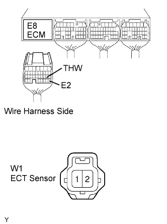 |
Disconnect the E8 ECM connector.
Disconnect the W1 sensor connector.
Measure the resistance of the wire harness side connectors.
| Tester Connection | Specified Condition |
| E8-19 (THW) - W1-2 (THW) | Below 1 Ω |
| E8-28 (E2) - W1-1 (E2) | Below 1 Ω |
| E8-19 (THW) or W1-2 (THW) - Body ground | 10 kΩ or higher |
| E8-28 (E2) or W1-1 (E2) - Body ground | 10 kΩ or higher |
|
| ||||
| OK | ||
| ||
