DTC P0110/24 Intake Air Temperature Circuit |
DTC P0112/24 Intake Air Temperature Circuit Low Input |
DTC P0113/24 Intake Air Temperature Circuit High Input |
| DTC No. | DTC Detection Condition | Trouble Area |
| P0110/24 | Open or short in IAT sensor circuit for 0.5 seconds (1 trip detection logic) |
|
| P0112/24 | Short in IAT sensor circuit for 0.5 seconds (1 trip detection logic) |
|
| P0113/24 | Open in IAT sensor circuit for 0.5 seconds (1 trip detection logic) |
|
| Temperature Displayed | Malfunction |
| -40°C (-40°F) | Open circuit |
| 140°C (284°F) or more | Short circuit |
| 1.READ DATA LIST (INTAKE AIR TEMPERATURE) |
Connect the intelligent tester to the DLC3.
Turn the ignition switch ON and turn the intelligent tester ON.
Enter the following menus: Powertrain / Engine / Data List / Intake Air.
Read the values.
| Temperature Displayed | Proceed to |
| -40°C (-40°F) | A |
| 140°C (284°F) or more | B |
| OK (same as air temperature near to intake manifold) | C |
|
| ||||
|
| ||||
| A | |
| 2.READ DATA LIST (CHECK FOR OPEN IN WIRE HARNESS) |
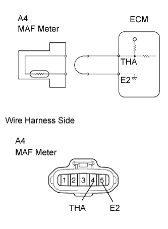 |
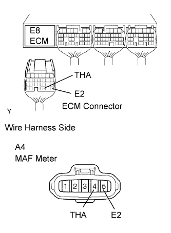
Disconnect the A4 MAF meter connector.
Connect terminals 4 and 5 of the MAF meter wire harness side connector.
Connect the intelligent tester to the DLC3.
Turn the ignition switch ON and turn the intelligent tester ON.
Enter the following menus: Powertrain / Engine / Data List / Intake Air.
Read the values.
|
| ||||
| NG | |
| 3.READ DATA LIST (CHECK FOR OPEN IN ECM) |
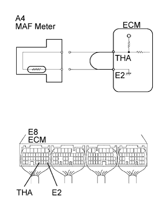 |
Disconnect the A4 MAF meter connector.
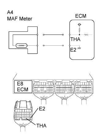
Connect terminals THA and E2 of the E8 ECM connector.
Connect the intelligent tester to the DLC3.
Turn the ignition switch ON and turn the intelligent tester ON.
Enter the following menus: Powertrain / Engine / Data List / Intake Air.
Read the values.
|
| ||||
| NG | ||
| ||
| 4.READ DATA LIST (CHECK FOR SHORT IN WIRE HARNESS) |
 |
Disconnect the A4 MAF meter.
Connect the intelligent tester to the DLC3.
Turn the ignition switch ON and turn the intelligent tester ON.
Enter the following menus: Powertrain / Engine / Data List / Intake Air.
Read the values.
|
| ||||
| NG | |
| 5.READ DATA LIST (CHECK FOR SHORT IN ECM) |
 |
Disconnect the A4 MAF meter.
Disconnect the E8 ECM connector.
Connect the intelligent tester to the DLC3.
Turn the ignition switch ON and turn the intelligent tester ON.
Enter the following menus: Powertrain / Engine / Data List / Intake Air.
Read the values.
|
| ||||
| NG | ||
| ||
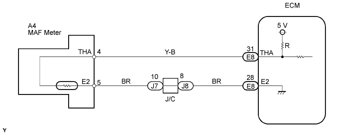
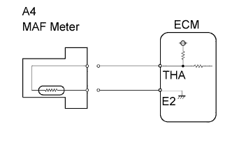
| 1.CHECK ECM (THA VOLTAGE) |
 |
Start the engine.
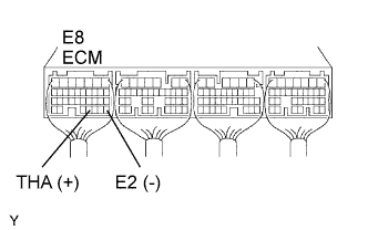
Measure the voltage of the ECM connector.
| Tester Connection | Condition | Specified Condition |
| E8-31 (THA) - E8-28 (E2) | Idling, IAT at 20°C (68°F) | 0.5 to 3.4 V |
|
| ||||
| NG | |
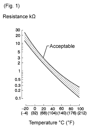
| 2.INSPECT INTAKE AIR TEMPERATURE SENSOR |
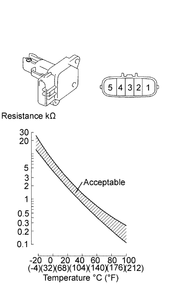 |
Remove the MAF meter.
Measure the resistance of the sensor.
| Tester Connection | Condition | Specified Condition |
| 4 - 5 | -20°C (-4°F) | 13.6 to 18.4 kΩ |
| 4 - 5 | 20°C (68°F) | 2.21 to 2.69 kΩ |
| 4 - 5 | 60°C (140°F) | 0.49 to 0.67 kΩ |
|
| ||||
| OK | |
| 3.CHECK WIRE HARNESS (ECM- INTAKE AIR TEMPERATURE SENSOR) |
 |
Disconnect the E8 ECM connector.
Disconnect the A4 MAF meter connector.
Measure the resistance of the wire harness side connectors.
| Tester Connection | Specified Condition |
| E8-31 (THA) - A4-4 (THA) | Below 1 Ω |
| E8-28 (E2) - A4-5 (E2) | Below 1 Ω |
| E8-31 (THA) or A4-4 (THA) - Body ground | 10 kΩ higher |
| E8-28 (E2) or A4-5 (E2) - Body ground | 10 kΩ higher |
|
| ||||
| OK | ||
| ||
