DTC    P0818    Driveline Disconnect Switch Input Circuit

for Preparation Click here


DESCRIPTION

The ECM detects the signal from the transfer neutral position switch.
This DTC indicates that the transfer neutral position switch remains ON.

DTC No.
DTC Detection Condition
Trouble Area
P0818
Transfer neutral position switch remains ON while vehicle is running under following conditions for 30 sec. (2 trip detection logic):
  1. Vehicle speed is 25 km/h (16 mph) or more
  2. Transfer shift lever is on H
  1. Short in transfer neutral position switch circuit
  2. Transfer neutral position switch
  3. ECM

MONITOR DESCRIPTION

The ECM detects whether or not the transfer shift lever is in neutral by monitoring the signal from the transfer neutral position switch.
If the ECM detects that the transfer shift lever is in neutral under the following conditions, the ECM will conclude that there is a malfunction of the transfer neutral position switch:
  1. Transfer neutral position switch indicates that the transfer shift lever is in neutral.
  2. Transfer shift lever is in the H position.
  3. The vehicle is traveling at 25 km/h (16 mph) or more.
  4. The transfer neutral position switch has been ON for more than 30 seconds.
If all of the above conditions are detected, the ECM will conclude that there is a malfunction of the transfer neutral position switch, illuminate the MIL and store the DTC.

WIRING DIAGRAM


A107752E01


INSPECTION PROCEDURE

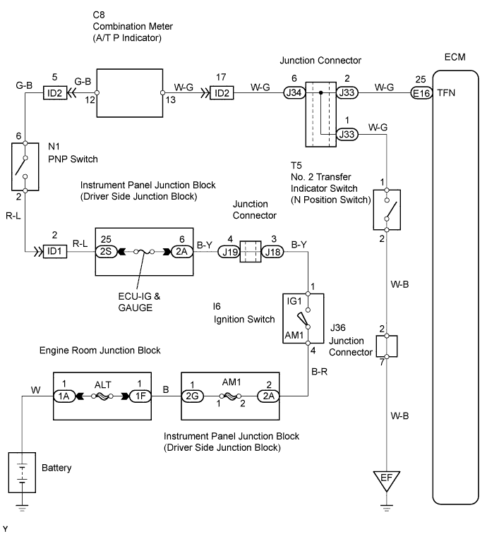
1.CHECK WIRE HARNESS (NO. 2 TRANSFER INDICATOR SWITCH - BODY GROUND)
G037538E01
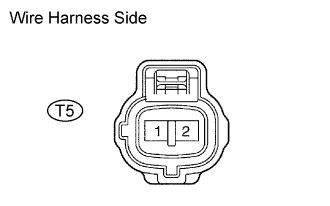
  1. Disconnect the T5 No. 2 transfer indicator switch connector.

  1. Measure the resistance of the wire harness side connector.

    Standard resistance:
    Transfer Connection
    Specified Condition
    T5-2 - Body ground
    Below 1 Ω


NG
REPLACE COMBINATION METER
OK


2.INSPECT NO. 2 TRANSFER INDICATOR SWITCH (TRANSFER NEUTRAL POSITION SWITCH)
A110992E01
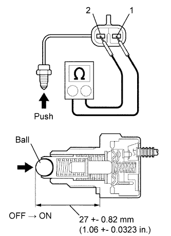
  1. Remove the transfer indicator switch.

  1. Measure the resistance of the switch when pushing the ball at the tip of the switch.

    Tester Connection
    Switch Condition
    Specified Condition
    1 - 2
    Not pushed
    10 kΩ or higher
    1 - 2
    Pushed
    Below 1 Ω


NG
REPLACE NO. 2 TRANSFER INDICATOR SWITCH (TRANSFER NEUTRAL POSITION SWITCH)
OK


3.INSPECT COMBINATION METER
  1. Check the A/T P indicator light.

    1. Disconnect the T5 transfer indicator switch connector.

    2. Turn the ignition switch ON.

    3. Connect the T5-1 terminal of the wire harness side connector to the body ground, and then check the A/T P indicator light.

      OK:
      A/T P indicator light illuminates.


NG
REPLACE COMBINATION METER
OK

REPAIR OR REPLACE HARNESS AND CONNECTOR