HOW TO TROUBLESHOOT ECU CONTROLLED SYSTEMS > HOW TO PROCEED WITH TROUBLESHOOTING


OPERATION FLOW

HINT:
Perform troubleshooting in accordance with the procedures below. The following is an outline of basic troubleshooting procedures. Confirm the troubleshooting procedures for the circuit you are working on before beginning troubleshooting.


1.VEHICLE BROUGHT TO WORKSHOP

    NEXT


    2.CUSTOMER PROBLEM ANALYSIS
    1. Ask the customer about the conditions and environment when the problem occurred.


    NEXT


    3.INSPECT BATTERY VOLTAGE

      Standard voltage:
      11 to 14 V

      If the voltage is below 11 V, recharge or replace the battery before proceeding.

    NEXT


    4.SYMPTOM CONFIRMATION AND DTC (AND FREEZE FRAME DATA) CHECK
    1. Visually check the wire harnesses, connectors and fuses for open and short circuits.

    2. Warm up the engine to the normal operating temperature.

    3. Confirm the problem symptoms and conditions, and check for DTCs.

      Result:
      Result
      Proceed to
      DTC is output
      A
      DTC is not output
      B


    B.
    Go to step 6
    A


    5.DTC CHART
    1. Check the results obtained in the DTC check. Then find the output DTC in the DTC chart. Look at the "Trouble Area" column for a list of potentially malfunctioning circuits and / or parts.


    NEXT.
    Go to step 7

    6.PROBLEM SYMPTOMS CHART
    1. Check the results obtained in the symptom confirmation. Then find the problem symptoms in the problem symptoms table. Look at the "Suspected Area" column for a list of potentially malfunctioning circuits and / or parts.


    NEXT


    7.CIRCUIT INSPECTION OR PARTS INSPECTION
    1. Confirm the malfunctioning circuit or part.


    NEXT


    8.ADJUST, REPAIR OR REPLACE
    1. Adjust, repair or replace the malfunctioning circuit or parts.


    NEXT


    9.CONFIRMATION TEST
    1. After the adjustment, repairs or replacement, confirm that the malfunction no longer exists. If the malfunction does not reoccur, perform a confirmation test under the same conditions and in the same environment as when the malfunction occurred the first time.


    NEXT

    END


    CUSTOMER PROBLEM ANALYSIS

    HINT:
    1. In troubleshooting, confirm that the problem symptoms have been accurately identified. Preconceptions should be discarded in order to make an accurate judgment. To clearly understand what the problem symptoms are, it is extremely important to ask the customer about the problem and the conditions at the time the malfunction occurred.
    2. Gather as much information as possible for reference. Past problems that seem unrelated may also help in some cases.

    1. The 5 following questions are important points in the problem analysis:

      What
      Vehicle model, system name
      When
      Date, time, occurrence frequency
      Where
      Road conditions
      Under what conditions?
      Running conditions, driving conditions, weather conditions
      How did it happen?
      Problem symptoms

    SYMPTOM CONFIRMATION AND DIAGNOSTIC TROUBLE CODE

    HINT:
    The diagnostic system in the HILUX has various functions.
    1. The first function is the Diagnostic Trouble Code (DTC) check. A DTC is a code stored in the ECU memory whenever a malfunction in the signal circuits to the ECU occurs. In a DTC check, a previous malfunction's DTC can be checked by a technician during troubleshooting.
    1. Another function is the Input Signal Check, which checks if the signals from various switches are sent to the ECU correctly.
      By using these functions, the problem areas can be narrowed down and troubleshooting is more effective. Diagnostic functions are incorporated in the following system in the HILUX.

      System
      DTC Check
      (Normal Mode)
      DTC Check
      (Check Mode)
      Freeze Frame Data
      Sensor Check/Test Mode (Input Signal Check)
      Data List
      Active Test
      Customize Parameter
      SFI System (1TR-FE, 2TR-FE)


      SFI System (1GR-FE)


      SFI System (1KD-FTV, 2KD-FTV)


      Electronic Controlled Automatic Transmission (A750E, A750F)


      Electronic Controlled Automatic Transmission (A340F)


      Airbag System


      Engine Immobiliser System


      Power Door Lock Control System


      Meter / Gauge System


      Power Window Control System


      Cruise Control System


    1. In the DTC check, it is very important to determine whether the problem indicated by the DTC is either: 1) still occurring, or 2) occurred in the past but has since returned to normal. In addition, the DTC should be compared to the problem symptom to see if they are related. For this reason, DTCs should be checked before and after confirmation of symptoms (i.e., whether or not problem symptoms exist) to determine current system conditions, as shown in the flowchart below.
    1. Never skip the DTC check. Failing to check DTCs may, depending on the case, result in unnecessary troubleshooting for systems operating normally or lead to procedures not related to the problem. Follow the procedures listed in the flowchart in the correct order.
    1. The following flowchart shows how to proceed with troubleshooting using the DTC check. Directions from the flowchart will indicate how to proceed either to DTC troubleshooting or to the troubleshooting of each problem symptom.


    1.DTC CHECK

      NEXT


      2.MAKE A NOTE OF DTCS DISPLAYED AND THEN CLEAR MEMORY

        NEXT


        3.SYMPTOM CONFIRMATION

          Result:
          Result
          Proceed to
          No symptoms exist
          A
          Symptoms exist
          B


        B.
        Go to step 5
        A


        4.SIMULATION TEST USING SYMPTOM SIMULATION METHODS

          NEXT


          5.DTC CHECK

            Result:
            Result
            Proceed to
            DTC is not output
            A
            DTC is output
            B


          B.
          TROUBLESHOOTING OF PROBLEM INDICATED BY DTC
          A


          6.SYMPTOM CONFIRMATION

            Result:
            Result
            Proceed to
            No symptoms exist
            A
            Symptoms exist
            B

            If a DTC was displayed in the initial DTC check, the problem may have occurred in a wire harness or connector in that circuit in the past. Check the wire harness and connectors.


          B.
          SYSTEM NORMAL
          A

          TROUBLESHOOTING OF EACH PROBLEM SYMPTOM

          The problem is still occurring in a place other than the diagnostic circuit (the DTC displayed first is either for a past problem or a secondary problem).

          SYMPTOM SIMULATION
          For example:
          With a problem that only occurs when the engine is cold or as a result of vibration caused by the road during driving, the problem cannot be determined if the symptoms are being checked on a stationary vehicle or a vehicle with a warmed-up engine. Vibration, heat or water penetration (moisture) is difficult to reproduce. The symptom simulation tests below are effective substitutes for the conditions and can be applied on a stationary vehicle. Important points in the symptom simulation test:
          In the symptom simulation test, the problem symptoms as well as the problem area or parts must be confirmed. First, narrow down the possible problem circuits according to the symptoms. Then, connect the tester and carry out the symptom simulation test, judging whether the circuit being tested is defective or normal. Also, confirm the problem symptoms at the same time. Refer to the problem symptoms table for each system to narrow down the possible causes.

          HINT:
          The most difficult case in troubleshooting is when no problem symptoms occur. In such a case, a thorough problem analysis must be carried out. A simulation of the same or similar conditions and environment in which the problem occurred in the customer's vehicle should be performed. No matter how much skill or experience a technician has, troubleshooting without confirming the problem symptoms will lead to important repairs being overlooked and mistakes or delays.


            B071602E03
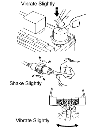
          1. VIBRATION METHOD: When a malfunction seems to occur as a result of vibration.

            1. PART AND SENSOR
              Apply slight vibration with a finger to the part of the sensor suspected to be the cause of the problem, and check whether or not the malfunction occurs.

              NOTICE:
              Applying strong vibration to relays may open relays.

            2. CONNECTORS
              Slightly shake the connector vertically and horizontally.

            3. WIRE HARNESS
              Slightly shake the wire harness vertically and horizontally.

              HINT:
              The connector joint and fulcrum of the vibration are the major areas that should be checked thoroughly.

          2. HEAT METHOD: When a malfunction seems to occur as a result of heat.

            1. Heat the component that is the possible cause of the malfunction with a hair dryer or similar device. Check if the malfunction occurs.

              NOTICE:
              1. Do not heat to more than 60°C (140°F). Exceeding this temperature may damage components.
              2. Do not apply heat directly to the parts in an ECU.


          3. D033373E01
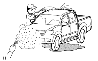
          4. WATER SPRINKLING METHOD: When a malfunction seems to occur on a rainy day or in high humidity.

            1. Sprinkle water onto the vehicle and check if the malfunction occurs.

              NOTICE:
              1. Never sprinkle water directly into the engine compartment. Indirectly change the temperature and humidity by spraying water onto the front of the radiator.
              2. Never apply water directly onto the electronic components.

              HINT:
              If the vehicle has or had a water leakage problem, the leakage may have damaged ECUs or connections. Look for evidence of corrosion or short circuits. Proceed with caution during water tests.


          5. B002389E02
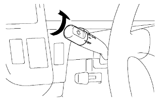
          6. HIGH ELECTRICAL LOAD METHOD: When a malfunction seems to occur when the electrical load is excessive.

            1. Turn on the heater blower, headlights, rear window defogger and all other electrical loads. Check if the malfunction occurs.


          DIAGNOSTIC TROUBLE CODE CHART
          Look for output Diagnostic Trouble Codes (DTCs) (from the DTC checks) in the appropriate section's Diagnostic Trouble Code Chart. Use the chart to determine the trouble area and the proper inspection procedure. A description of each of the chart's columns is below.

          Item
          Description
          DTC No.
          Indicates the diagnostic trouble code
          Detection Item
          Indicates the system or details of the problem
          Trouble Area
          Indicates the suspected areas of the problem
          See Page
          Indicates the page where the inspection procedures for each circuit can be found, or gives instructions for checking and repairs.

          PROBLEM SYMPTOMS TABLE
          When a "Normal" code is output during a DTC check but the problem is still occurring, use the Problem Symptoms Table. The suspected areas (circuits or parts) for each problem symptom are in the table. The suspected areas are listed in order of probability. A description of each of the chart's columns is below.

          HINT:
          In some cases, the problem is not detected by the diagnostic system even though a problem symptom is present. It is possible that the problem is occurring outside the detection range of the diagnostic system, or that the problem is occurring in a completely different system.


          Item
          Description
          Problem Symptom
          -
          Circuit Inspection, Inspection Order
          Indicates the order in which the circuits need to be checked
          Circuit or Part Name
          Indicates the circuit or part which needs to be checked
          See Page
          Indicates the page where the flowchart for each circuit is located

          CIRCUIT INSPECTION
          A description of the main areas of each circuit inspection is below.

          Item
          Description
          Circuit Description
          The major role of the circuit, its operation and its component parts are explained.
          Diagnostic Trouble Code No. and Detection item
          Indicates the diagnostic trouble codes, diagnostic trouble code settings and suspected areas for a problem.
          Wiring diagram
          This shows a wiring diagram of the circuit.
          Use this diagram together with an ELECTRICAL WIRING DIAGRAM to thoroughly understand the circuit.
          The first letter indicates the basic wire color and the second letter indicates the color of the stripe.
          Inspection Procedures
          Use the inspection procedures to determine if the circuit is normal or abnormal. If abnormal, use the inspection procedures to determine whether the problem is located in the sensors, actuators, wire harnesses or ECU.
          Indicates the condition of the connector of the ECU during the check
          Connector being checked is connected.
          Connections of tester are indicated by (+) or (-) after the terminal name.
          Connector being checked is disconnected.
          For illustrations of inspections between a connector and body ground, information about the body ground is not shown in the illustration.