CAMSHAFT > INSPECTION |
| 1. INSPECT VALVE LASH ADJUSTER |
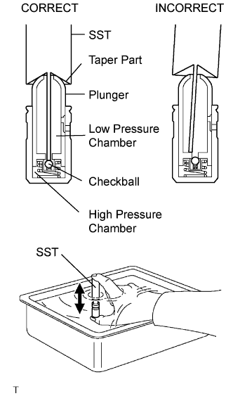 |
Place the lash adjuster into a container full of engine oil.
Insert SST's tip into the lash adjuster's plunger and use the tip to press down on the checkball inside the plunger.
Squeeze the SST and lash adjuster together to move the plunger up and down 5 to 6 times.
Check the movement of the plunger and bleed air.
After bleeding air, remove SST. Then, try to quickly and firmly press the plunger with a finger.
| 2. INSPECT CAMSHAFT TIMING GEAR |
 |
Check the lock of the camshaft timing gear.
Clamp the camshaft in a vise, and confirm that the camshaft timing gear is locked.
Release the lock pin.
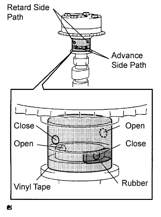
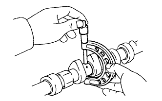
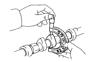
Cover the 4 oil paths of the cam journal with vinyl tape as shown in the illustration.
Break through the tape of the advance side path and the retard side path on the opposite side of the groove.
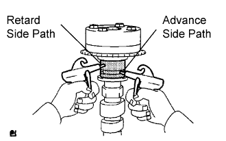 |
Apply approximately 200 kPa (2.0 kgf/cm2, 28 psi) of air pressure to the paths whose tape was broken in the procedure above.
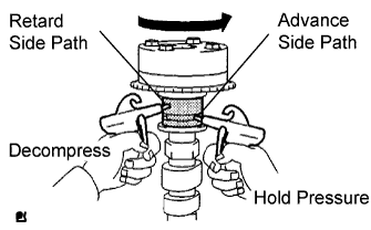 |
Check that the camshaft timing gear revolves in the advance direction when weakening the air pressure of the retard side path.
When the camshaft timing gear reaches the extreme advance position, remove the air gun from the retard side path and advance side path, in that order.
Check for smooth rotation.
Rotate the camshaft timing gear within its movable range several times, but do not turn it to the extreme retard position. Check that the gear rotates smoothly.
Check the lock in the extreme retard position.
Confirm that the camshaft timing gear is locked at the extreme retard position.
| 3. INSPECT NO. 1 CAMSHAFT |
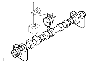 |
Check the camshaft for runout.
Place the camshaft on V-blocks.
Using a dial indicator, measure the circle runout at the center journal.
 |
Using a micrometer, measure the cam lobe height.
 |
Using a micrometer, measure the journal diameter.
| Journal | Diameter |
| No. 1 journal | 35.949 to 35.965 mm (1.4153 to 1.4159 in.) |
| Other journal | 26.959 to 26.975 mm (1.0614 to 1.0620 in.) |
| 4. INSPECT NO. 2 CAMSHAFT |
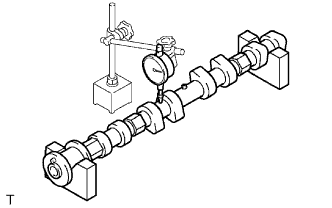 |
Check the camshaft for runout.
Place the camshaft on V-blocks.
Using a dial indicator, measure the circle runout at the center journal.
 |
Using a micrometer, measure the cam lobe height.
|
Using a micrometer, measure the journal diameter.
| Journal | Diameter |
| No. 1 journal | 35.949 to 35.965 mm (1.4153 to 1.4159 in.) |
| Other journal | 26.959 to 26.975 mm (1.0614 to 1.0620 in.) |
