AIR CONDITIONING UNIT > INSTALLATION |
| 1. INSTALL AIR CONDITIONING UNIT ASSEMBLY |
 |
Install the A/C unit with the bolt and nut.
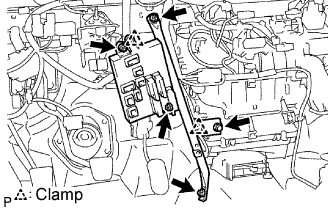
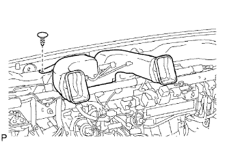
| 2. INSTALL INSTRUMENT PANEL REINFORCEMENT |
Install the instrument panel reinforcement with the 7 bolts.
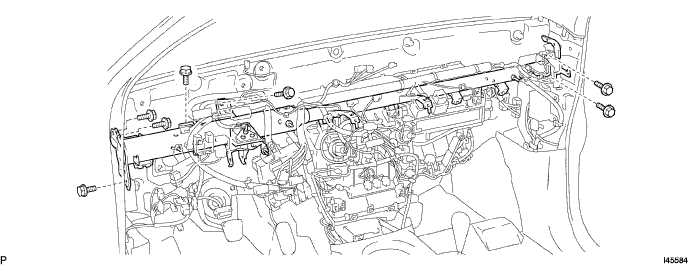
Install the 3 bolts.
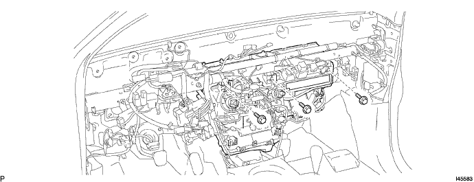
Connect the connectors.
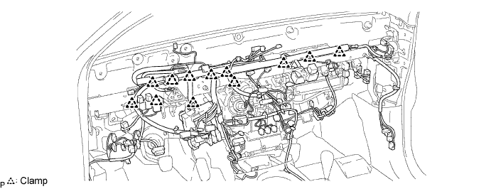
Attach the 12 clamps.
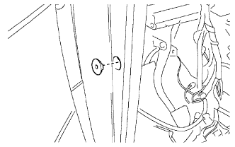 |
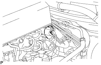
Install the grommet to the vehicle body.
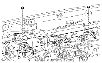 |
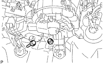
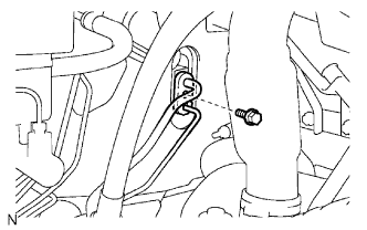
Connect the ground wires to the instrument panel reinforcement with the 2 bolts.
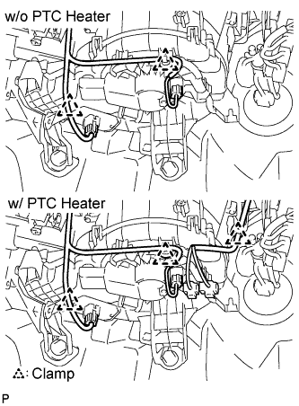 |
Connect the connector and wire harness.
w/o PTC heater:
Attach the 2 clamps.
w/ PTC heater:
Attach the 3 clamps.
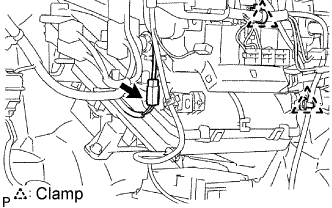 |
Connect the connector and wire harness.
Attach the 2 clamps.
| 3. INSTALL NO.1 COOLER UNIT DRAIN HOSE |
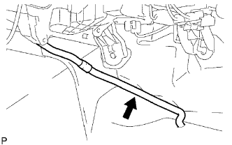 |
Install the drain hose.
| 4. INSTALL AIR CONDITIONING AMPLIFIER ASSEMBLY (w/ Air Conditioning) |
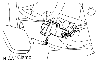 |
Install the A/C amplifier with the screw.
Connect the connector.
Attach the clamp to install the amplifier.
| 5. INSTALL NO. 4 AIR DUCT |
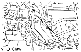 |
Attach the 2 claws to install the duct.
| 6. INSTALL NO. 2 AIR DUCT |
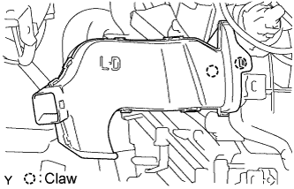 |
Attach the 2 claws to install the duct.
| 7. INSTALL NO. 1 AIR DUCT |
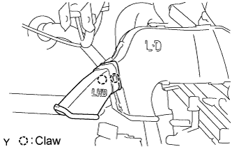 |
Attach the 2 claws to install the duct.
| 8. INSTALL ECM |
| 9. INSTALL STEERING COLUMN ASSEMBLY |
Install the steering column with the 3 bolts.
| 10. INSTALL NO. 1 INSTRUMENT PANEL BRACE SUB-ASSEMBLY |
 |
Connect the connectors to install the instrument panel junction block.
Attach the 2 clamps to install the brace.
Install the brace with the 3 nuts and 2 bolts.
| 11. INSTALL NO. 3 HEATER TO REGISTER DUCT |
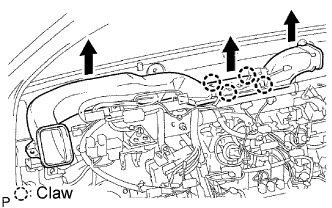 |
Attach the 4 claws to install the duct.
| 12. INSTALL NO. 1 HEATER TO REGISTER DUCT |
 |
Attach the 3 claws to install the duct.
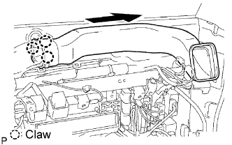
| 13. INSTALL NO. 2 HEATER TO REGISTER DUCT |
 |
Install the clip and duct.
| 14. INSTALL INSTRUMENT PANEL SUB-ASSEMBLY LOWER |
Install the instrument panel sub-assembly lower (Click here).
| 15. INSTALL INSTRUMENT PANEL SUB-ASSEMBLY UPPER |
Install the instrument panel sub-assembly upper (Click here).
| 16. CONNECT WATER HOSE SUB-ASSEMBLY |
 |
Connect the water hose and attach the clip.
| 17. CONNECT WATER HOSE SUB-ASSEMBLY B |
| 18. CONNECT AIR CONDITIONING TUBE AND ACCESSORY ASSEMBLY (w/ Air Conditioning) |
Remove the vinyl tape attached to the tube.
Sufficiently apply compressor oil to 2 new O-rings and the fitting surface of the A/C tube.
Install the 2 O-rings on the A/C tube.
Connect the A/C tube & accessory and attach the piping clamp.
| 19. CONNECT SUCTION TUBE SUB-ASSEMBLY (w/ Air Conditioning) |
 |
Remove the vinyl tape attached to the tube.
Sufficiently apply compressor oil to 2 new O-rings and the fitting surface of the suction tube.
Install the 2 O-rings on the suction tube.
Connect the suction tube and attach the piping clamp.
| 20. CONNECT CABLE TO NEGATIVE BATTERY TERMINAL |
| 21. PERFORM INITIALIZATION |
Perform initialization (Click here).
| 22. CHECK SRS WARNING LIGHT |
Check the SRS warning light (Click here).
| 23. ADD ENGINE COOLANT |
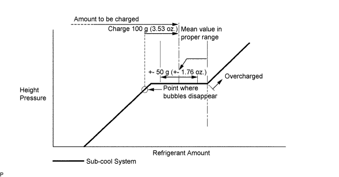
| 24. CHARGE REFRIGERANT |
Perform vacuum purging using a vacuum pump.
Charge refrigerant HFC-134a (R134a).
| 25. WARM UP ENGINE |
Warm up the engine at less than 1,850 rpm for 2 minutes or more after charging refrigerant.
| 26. CHECK FOR ENGINE COOLANT LEAKS |
| 27. CHECK FOR LEAKAGE OF REFRIGERANT |
After recharging the refrigerant gas, check for refrigerant gas leakage using a halogen leak detector.
Perform the operation under these conditions:
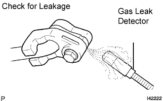 |
Using a gas leak detector, check the refrigerant line for leakage.
If a gas leak is not detected on the drain hose, remove the blower motor control (blower resistor) from the cooling unit. Insert the gas leak detector sensor into the unit and perform the test.
Disconnect the connector and leave the pressure switch on for approximately 20 minutes. Bring the gas leak detector close to the pressure switch and perform the test.
