AIR CONDITIONING AND BLOWER UNIT > INSTALLATION |
| 1. INSTALL AIR CONDITIONING AND BLOWER ASSEMBLY |
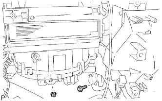 |
Install the A/C unit with the bolt and nut.
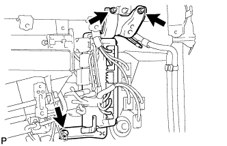
| 2. INSTALL INSTRUMENT PANEL REINFORCEMENT |
Install the instrument panel reinforcement with the 7 bolts.
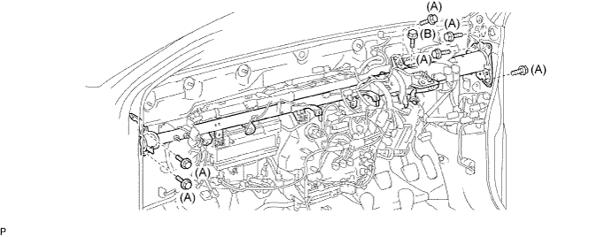
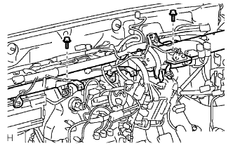
Install the 3 bolts.
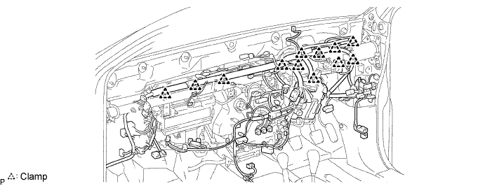
Install the 12 clamps.
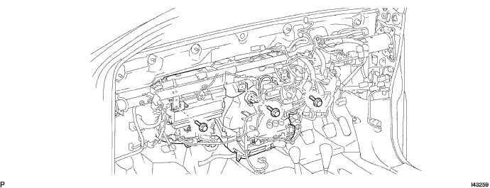
Connect the connectors.
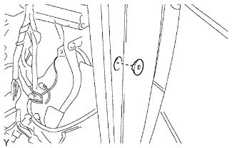 |
Install the grommet.
 |
Install the ground wires with the 2 bolts to the instrument panel reinforcement.
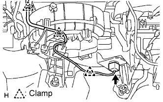 |
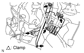
Connect the connector, 3 clamps and wire harness.
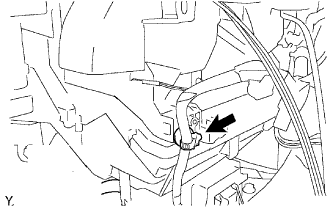 |
Attach the clamp to the A/C unit.
| 3. INSTALL ECM |
 |
Install the ECM with the bolt and 2 nuts.
Connect the 4 connectors.
| 4. INSTALL STEERING COLUMN ASSEMBLY |
Install the steering column with the 3 bolts.
| 5. INSTALL NO. 1 COOLER UNIT DRAIN HOSE |
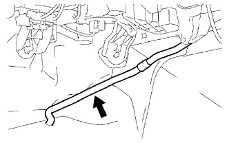 |
Install the drain hose.
| 6. INSTALL NO. 1 INSTRUMENT PANEL BRACE SUB-ASSEMBLY |
 |
Install the 3 nuts , 2 bolts, 2 clamps and instrument panel brace.
Connect the connectors and install the instrument panel junction block.
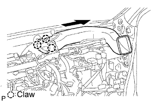
| 7. INSTALL NO. 3 HEATER TO REGISTER DUCT |
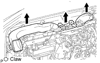 |
Attach the 4 claws and install the duct.
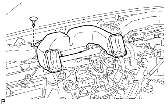
| 8. INSTALL NO. 1 HEATER TO REGISTER DUCT |
 |
Attach the 3 claws and install the duct.
| 9. INSTALL NO. 2 HEATER TO REGISTER DUCT |
 |
Install the duct with the clip.
| 10. INSTALL INSTRUMENT PANEL SUB-ASSEMBLY LOWER |
Install the instrument panel sub-assembly lower (Click here).
| 11. INSTALL INSTRUMENT PANEL SUB-ASSEMBLY UPPER |
Install the instrument panel sub-assembly upper (Click here).
| 12. CONNECT CABLE TO NEGATIVE BATTERY TERMINAL |
| 13. PERFORM INITIALIZATION |
Perform initialization (Click here).
| 14. CHECK SRS WARNING LIGHT |
Check the SRS warning light (Click here).
