POWER DOOR LOCK CONTROL SYSTEM > All Doors cannot be Locked / Unlocked Simultaneously |
| 1.CHECK DOOR LOCK / UNLOCK OPERATION |
Proceed to the next step according to the system listed in the table below.
| Symptom | Proceed to |
| All doors cannot be locked / unlocked at once using door control switch on master switch (switch operation) | A |
| All doors cannot be locked / unlocked at once using door key cylinder on driver side (key operation) | B |
| Only one door cannot be locked / unlocked | C |
| All symptoms listed above are present | D |
|
| ||||
|
| ||||
|
| ||||
| A | |
| 2.INSPECT POWER WINDOW REGULATOR MASTER SWITCH ASSEMBLY (DOOR CONTROL SWITCH) |
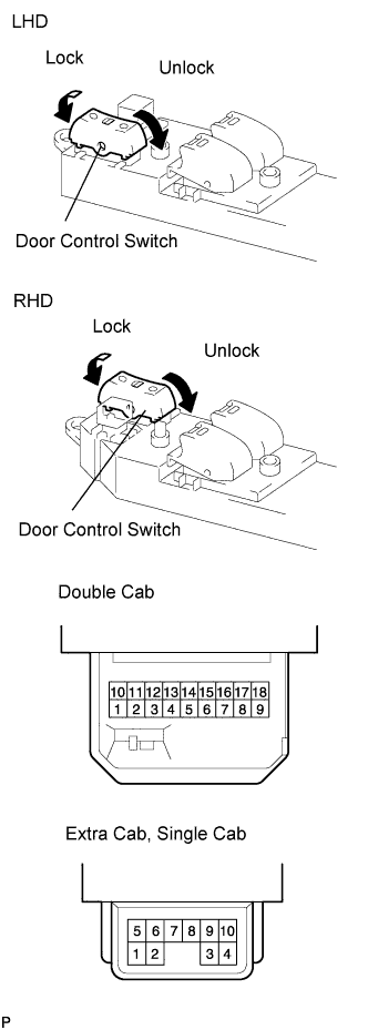 |
Measure the resistance of the door control switch.
| Tester Connection | Switch Condition | Specified Condition |
| 3 - 5 | Lock | Below 1 Ω |
| 3 - 5, 3 - 8 | OFF | 10 kΩ or higher |
| 3 - 8 | Unlock | Below 1 Ω |
| Tester Connection | Switch Condition | Specified Condition |
| 1 - 2 | Lock | Below 1 Ω |
| 1 - 2, 1 - 5 | OFF | 10 kΩ or higher |
| 1 - 5 | Unlock | Below 1 Ω |
| Tester Connection | Switch Condition | Specified Condition |
| 3 - 10 | Lock | Below 1 Ω |
| 3 - 10, 4- 10 | OFF | 10 kΩ or higher |
| 4 - 10 | Unlock | Below 1 Ω |
|
| ||||
| OK | |
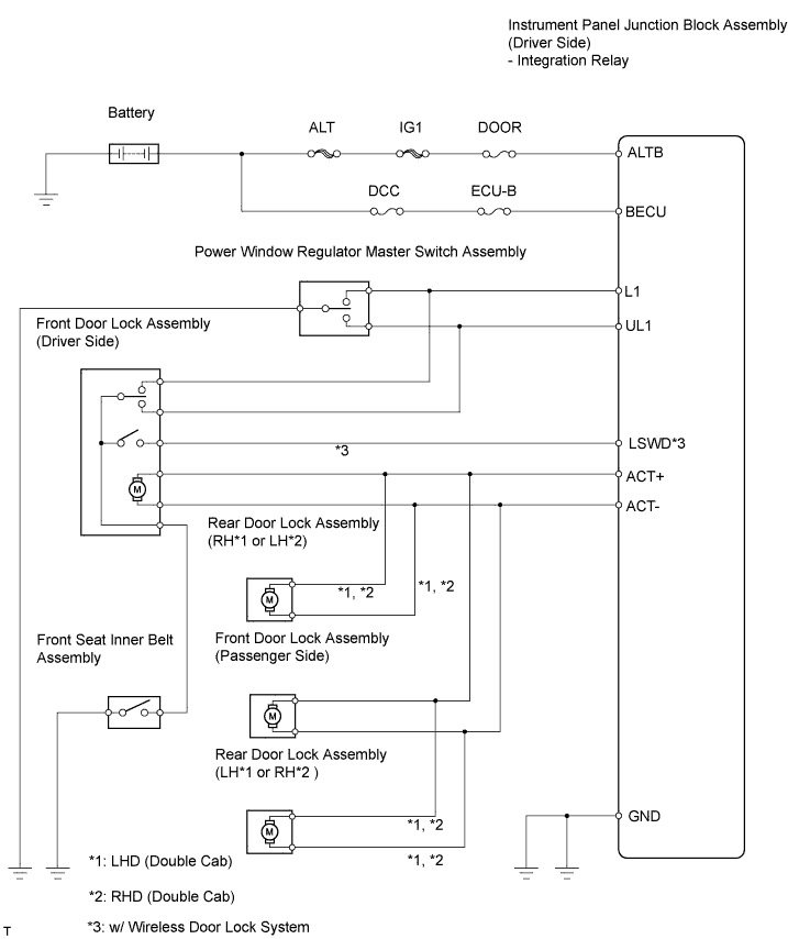
| 3.CHECK WIRE HARNESS (POWER WINDOW REGULATOR MASTER SWITCH ASSEMBLY - INSTRUMENT PANEL JUNCTION BLOCK ASSEMBLY (INTEGRATION RELAY) AND BODY GROUND) |
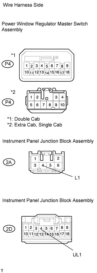 |
Disconnect the P4 switch connector.
Disconnect the 2A and 2D junction block connectors.
Measure the resistance of the wire harness side connectors.
| Tester Connection | Specified Condition |
| P4-5 - 2A-4 (L1) | Below 1 Ω |
| P4-8 - 2D-4 (UL1) | Below 1 Ω |
| P4-3 - Body ground | Below 1 Ω |
| P4-5 or 2A-4 (L1) - Body ground | 10 kΩ or higher |
| P4-8 or 2D-4 (UL1) - Body ground | 10 kΩ or higher |
| Tester Connection | Specified Condition |
| P4-2 - 2A-4 (L1) | Below 1 Ω |
| P4-5 - 2D-4 (UL1) | Below 1 Ω |
| P4-1 - Body ground | Below 1 Ω |
| P4-2 or 2A-4 (L1) - Body ground | 10 kΩ or higher |
| P4-5 or 2D-4 (UL1) - Body ground | 10 kΩ or higher |
| Tester Connection | Specified Condition |
| P4-3 - 2A-4 (L1) | Below 1 Ω |
| P4-4 - 2D-4 (UL1) | Below 1 Ω |
| P4-10 - Body ground | Below 1 Ω |
| P4-3 or 2A-4 (L1) - Body ground | 10 kΩ or higher |
| P4-4 or 2D-4 (UL1) - Body ground | 10 kΩ or higher |
|
| ||||
| OK | ||
| ||
| 4.INSPECT FRONT DOOR LOCK ASSEMBLY (DRIVER SIDE (DOOR LOCK MOTOR, DOOR LOCK AND UNLOCK SWITCH)) |
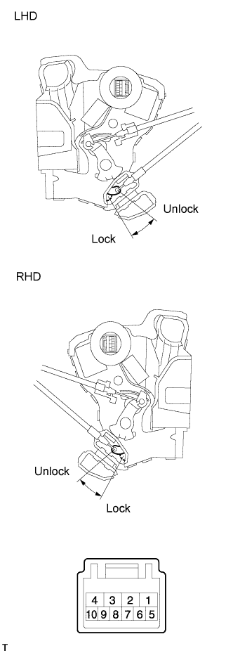 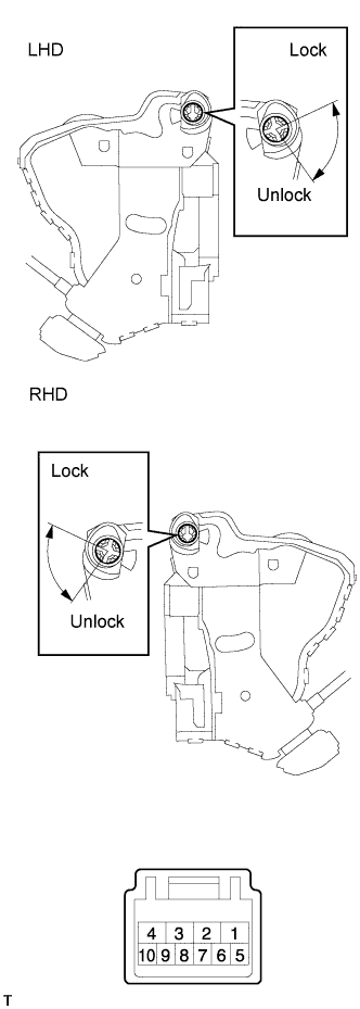 |
Apply battery voltage to the door lock and check operation of the door lock motor.
| Measurement Condition | Specified Condition |
| Battery positive (+) → Terminal 4 Battery negative (-) → Terminal 1 | Lock |
| Battery positive (+) → Terminal 1 Battery negative (-) → Terminal 4 | Unlock |
Measure the resistance of the door lock and unlock switch.
| Tester Connection | Door Lock Condition | Specified Condition |
| 7 - 9 | Lock | Below 1 Ω |
| 7 - 9, 7 - 10 | OFF | 10 kΩ or higher |
| 7 - 10 | Unlock | Below 1 Ω |
| Tester Connection | Door Lock Condition | Specified Condition |
| 6 - 8 | Lock | Below 1 Ω |
| 5 - 8, 6- 8 | OFF | 10 kΩ or higher |
| 5 - 8 | Unlock | Below 1 Ω |
w/ Wireless door lock system:
Measure the resistance of the position switch.
| Tester Connection | Switch Condition | Specified Condition |
| 7 - 8 | Lock | 10 kΩ or higher |
| 7 - 8 | Unlock | Below 1 Ω |
|
| ||||
| OK | |
| 5.INSPECT FRONT SEAT INNER BELT ASSEMBLY (DRIVER SIDE) |
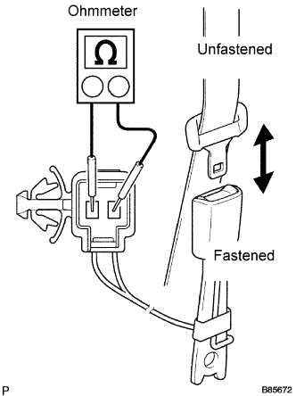 |
Measure the resistance of the buckle switch.
| Tester Connection | Condition | Specified Condition |
| 1 - 2 | Seat belt is unfastened | Below 1 Ω |
| 1 - 2 | Seat belt is fastened | 1 MΩ or higher |
|
| ||||
| OK | |
| 6.CHECK WIRE HARNESS (FRONT DOOR LOCK ASSEMBLY DRIVER SIDE - INSTRUMENT PANEL JUNCTION BLOCK ASSEMBLY (INTEGRATION RELAY) AND BODY GROUND) |
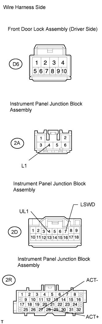 |
Disconnect the D6 door lock connectors.
Disconnect the 2A, 2D and 2R junction block connector.
Measure the resistance of the wire harness side connectors.
| Tester Connection | Condition | Specified Condition |
| D6-1 - 2R-27 (ACT-) | Always | Below 1 Ω |
| D6-4 - 2R-28 (ACT+) | Always | Below 1 Ω |
| D6-10 - 2D-4 (UL1) | Always | Below 1 Ω |
| D6-9 - 2A-4 (L1) | Always | Below 1 Ω |
| D6-7 - Body ground | Driver seat belt is not fastened | Below 1 Ω |
| D6-1 or 2R-27 (ACT-) - Body ground | Always | 10 kΩ or higher |
| D6-4 or 2R-28 (ACT+) - Body ground | Always | 10 kΩ or higher |
| D6-10 or 2D-4 (UL1) - Body ground | Always | 10 kΩ or higher |
| D6-9 or 2A-4 (L1) - Body ground | Always | 10 kΩ or higher |
| Tester Connection | Condition | Specified Condition |
| D6-1 - 2R-27 (ACT-) | Always | Below 1 Ω |
| D6-4 - 2R-28 (ACT+) | Always | Below 1 Ω |
| D6-5 - 2D-4 (UL1) | Always | Below 1 Ω |
| D6-6 - 2A-4 (L1) | Always | Below 1 Ω |
| D6-7 - 2D-7 (LSWD)* | Always | Below 1 Ω |
| D6-8 - Body ground | Driver seat belt is not fastened | Below 1 Ω |
| D6-1 or 2R-27 (ACT-) - Body ground | Always | 10 kΩ or higher |
| D6-4 or 2R-28 (ACT+) - Body ground | Always | 10 kΩ or higher |
| D6-5 or 2D-4 (UL1) - Body ground | Always | 10 kΩ or higher |
| D6-6 or 2A-4 (L1) - Body ground | Always | 10 kΩ or higher |
| D6-7 or 2D-7 (LSWD) - Body ground* | Always | 10 k Ω or higher |
|
| ||||
| OK | ||
| ||
| 7.INSPECT DOOR LOCK ASSEMBLY (DRIVER SIDE, PASSENGER SIDE, REAR LH AND REAR RH) |
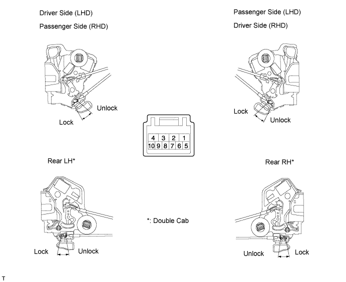
Apply battery voltage to the door lock and check operation of the door lock motor.
| Measurement Condition | Specified Condition |
| Battery positive (+) → Terminal 4 Battery negative (-) → Terminal 1 | Lock |
| Battery positive (+) → Terminal 1 Battery negative (-) → Terminal 4 | Unlock |
|
| ||||
| OK | |
| 8.CHECK WIRE HARNESS (DOOR LOCK ASSEMBLY - INSTRUMENT PANEL JUNCTION BLOCK ASSEMBLY (INTEGRATION RELAY) AND BODY GROUND) |
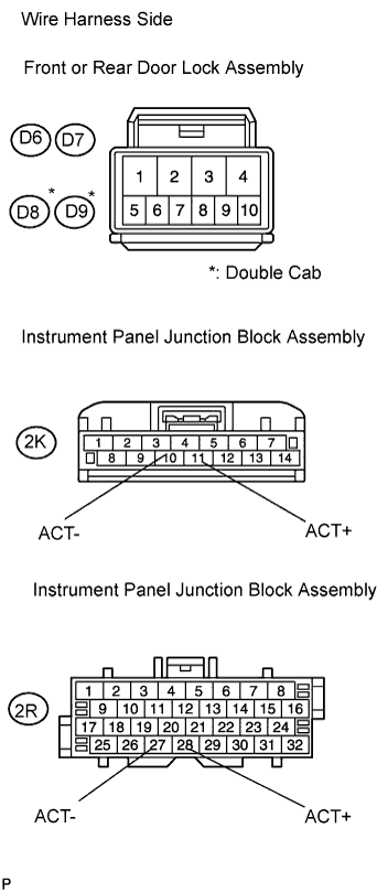 |
Disconnect the D6, D7, D8* or D9* door lock connector.
Disconnect the 2K or 2R junction block connector.
Measure the resistance of the wire harness side connectors.
| Tester Connection | Specified Condition |
| D6-4 - 2R-28 (ACT+) | Below 1 Ω |
| D6-1 - 2R-27 (ACT-) | Below 1 Ω |
| D7-4 - 2K-11 (ACT+) | Below 1 Ω |
| D7-1 - 2K-10 (ACT-) | Below 1 Ω |
| D8-4 - 2R-28 (ACT+)* | Below 1 Ω |
| D8-1 - 2R-28 (ACT-)* | Below 1 Ω |
| D9-4 - 2K-11 (ACT+)* | Below 1 Ω |
| D9-1 - 2K-10 (ACT-)* | Below 1 Ω |
| D6-4 or 2R-28 (ACT+) - Body ground | 10 kΩ or higher |
| D6-1 or 2R-27 (ACT-) - Body ground | 10 kΩ or higher |
| D7-4 or 2K-11 (ACT+) - Body ground | 10 kΩ or higher |
| D7-1 or 2K-10 (ACT-) - Body ground | 10 kΩ or higher |
| D8-4 or 2R-28 (ACT+) - Body ground* | 10 kΩ or higher |
| D8-1 or 2R-27 (ACT-) - Body ground* | 10 kΩ or higher |
| D9-4 or 2K-11 (ACT+) - Body ground* | 10 kΩ or higher |
| D9-1 or 2K-10 (ACT-) - Body ground* | 10 kΩ or higher |
| Tester Connection | Specified Condition |
| D6-4 - 2R-28 (ACT+) | Below 1 Ω |
| D6-1 - 2R-27 (ACT-) | Below 1 Ω |
| D7-4 - 2K-11 (ACT+) | Below 1 Ω |
| D7-1 - 2K-10 (ACT-) | Below 1 Ω |
| D8-4 - 2K-11 (ACT+)* | Below 1 Ω |
| D8-1 - 2K-10 (ACT-)* | Below 1 Ω |
| D9-4 - 2R-28 (ACT+)* | Below 1 Ω |
| D9-1 - 2R-27 (ACT-)* | Below 1 Ω |
| D6-4 or 2R-28 (ACT+) - Body ground | 10 kΩ or higher |
| D6-1 or 2R-27 (ACT-) - Body ground | 10 kΩ or higher |
| D7-4 or 2K-11 (ACT+) - Body ground | 10 kΩ or higher |
| D7-1 or 2K-10 (ACT-) - Body ground | 10 kΩ or higher |
| D8-4 or 2K-11 (ACT+) - Body ground* | 10 kΩ or higher |
| D8-1 or 2K-10 (ACT-) - Body ground* | 10 kΩ or higher |
| D9-4 or 2R-28 (ACT+) - Body ground* | 10 kΩ or higher |
| D9-1 or 2R-28 (ACT-) - Body ground* | 10 kΩ or higher |
|
| ||||
| OK | ||
| ||
| 9.INSPECT FUSE (ECU-B, DCC, DOOR) |
Remove the ECU-B and DCC fuses from the engine room relay block.
Remove the DOOR fuse from the No. 3 relay block.
Measure the resistance of the fuses.
|
| ||||
| OK | |
| 10.CHECK WIRE HARNESS (INSTRUMENT PANEL JUNCTION BLOCK ASSEMBLY (INTEGRATION RELAY) - BATTERY AND BODY GROUND) |
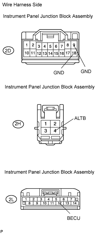 |
Disconnect the 2D, 2H and 2L junction block connectors.
Measure the voltage and resistance of the wire harness side connectors.
| Tester Connection | Specified Condition |
| 2L-12 (BECU) - Body ground | 10 to 14 V |
| 2H-4 (ALTB) - Body ground | 10 to 14 V |
| Tester Connection | Specified Condition |
| 2D-9 (GND) - Body ground | Below 1 Ω |
| 2D-18 (GND) - Body ground | Below 1 Ω |
|
| ||||
| OK | |
| 11.CHECK WIRE HARNESS (POWER WINDOW REGULATOR MASTER SWITCH ASSEMBLY - INSTRUMENT PANEL JUNCTION BLOCK ASSEMBLY (INTEGRATION RELAY) AND BODY GROUND) |
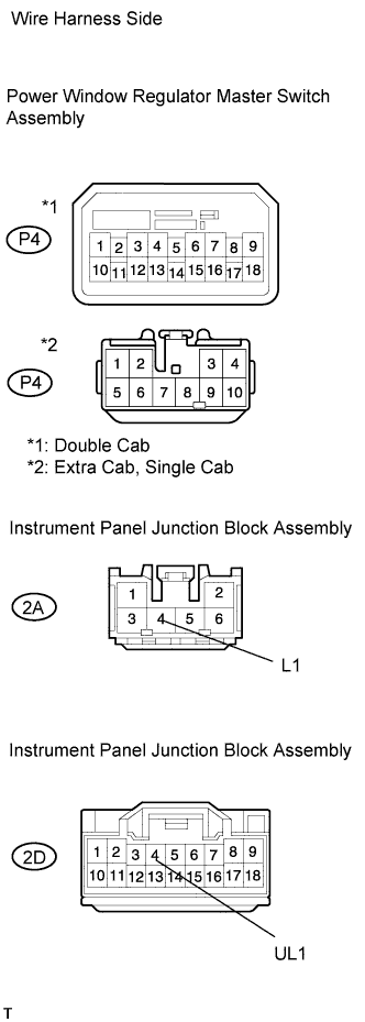 |
Disconnect the P4 switch connector.
Disconnect the 2A and 2D junction block connectors.
Measure the resistance of the wire harness side connectors.
| Tester Connection | Specified Condition |
| P4-5 - 2A-4 (L1) | Below 1 Ω |
| P4-8 - 2D-4 (UL1) | Below 1 Ω |
| P4-3 - Body ground | Below 1 Ω |
| P4-5 or 2A-4 (L1) - Body ground | 10 kΩ or higher |
| P4-8 or 2D-4 (UL1) - Body ground | 10 kΩ or higher |
| Tester Connection | Specified Condition |
| P4-2 - 2A-4 (L1) | Below 1 Ω |
| P4-5 - 2D-4 (UL1) | Below 1 Ω |
| P4-1 - Body ground | Below 1 Ω |
| P4-2 or 2A-4 (L1) - Body ground | 10 kΩ or higher |
| P4-5 or 2D-4 (UL1) - Body ground | 10 kΩ or higher |
| Tester Connection | Specified Condition |
| P4-3 - 2A-4 (L1) | Below 1 Ω |
| P4-4 - 2D-4 (UL1) | Below 1 Ω |
| P4-10 - Body ground | Below 1 Ω |
| P4-3 or 2A-4 (L1) - Body ground | 10 kΩ or higher |
| P4-4 or 2D-4 (UL1) - Body ground | 10 kΩ or higher |
|
| ||||
| OK | ||
| ||
