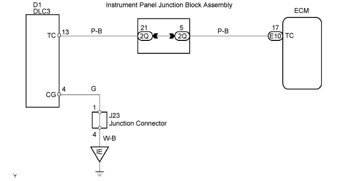
SFI SYSTEM > TC and CG Terminal Circuit

for Preparation Click here


DESCRIPTION

Terminals TC and CG are located in the DLC3. When connecting these terminals, DTCs in normal mode or check mode can be determined through MIL flashing patterns in the combination meter.

WIRING DIAGRAM


A099746E02


INSPECTION PROCEDURE

HINT:
If either of the following symptoms is present, it is determined that an open or a short in the wire harness has occurred, or there has been a malfunction in the ECM.
  1. The MIL displaying function does not work even though terminals TC and CG of the DLC3 are connected.
  2. The MIL flashes even though terminals TC and CG of the DLC3 are not connected.

1.CHECK DLC3 (TC VOLTAGE)
A082779E46
  1. Turn the ignition switch ON.

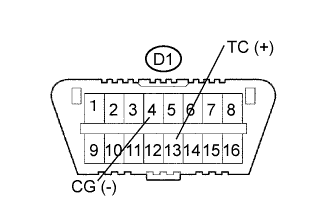
  1. Measure the voltage of the DLC3.

    Standard voltage:
    Tester Connection
    Specified Condition
    D1-13 (TC) - D1-4 (CG)
    9 to 14 V


OK
Go to step 3
NG


2.CHECK WIRE HARNESS (DLC3 - ECM)
G034707E01
  1. Disconnect the E10 ECM connector.

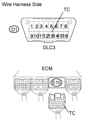
  1. Measure the resistance of the wire harness side connectors.

    Standard resistance:
    Tester Connection
    Specified Condition
    D1-13 (TC) - E10-17 (TC)
    Below 1 Ω
    D1-13 (TC) or E10-17 (TC) - Body ground
    10 kΩ or higher


NG
REPAIR OR REPLACE HARNESS AND CONNECTOR (DLC3 - ECM)
OK

REPAIR OR REPLACE HARNESS AND CONNECTOR (DLC3 - BODY GROUND) 

3.CHECK IF MIL BLINKS
A082779E45
  1. Turn the ignition switch ON.

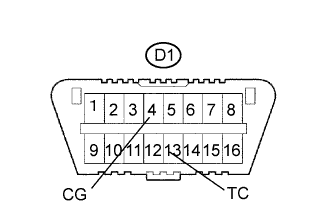
  1. Using SST, connect terminals TC and CG of the D1 DLC3 connector.

  1. Check that the MIL blinks.

    OK:
    The MIL blinks.

SST
09843-18040  


NG
REPLACE ECM
OK

NO PROBLEM