DECELERATION SENSOR (for 4WD) > ON-VEHICLE INSPECTION |
| 1. INSPECT DECELERATION SENSOR |
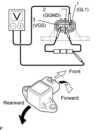 |
Connect 3 dry cell batteries of 1.5 V in series.
Connect the batteries' positive (+) lead to terminal 3 (VGS) and the negative (-) lead to terminal 2 (GGND).
Connect the voltmeter's positive (+) lead to the negative (-) lead of the batteries, and the positive (-) lead to terminal 1 (GL1). Apply approximately 4.5 V.
Check the output voltage of terminal 1 (GL1) when the sensor is tilted forward and rearward.
| Tester Connection | Sensor Position | Specified Condition |
| 1 (GL1) - Battery's negative (-) lead | Horizontal | Approx. 2.5 V |
| 1 (GL1) - Battery's negative (-) lead | Tilted forward | Approx. 0.5 to 2.5 V |
| 1 (GL1) - Battery's negative (-) lead | Tilted rearward | Approx. 2.5 to 4.5 V |
