METER / GAUGE SYSTEM > ON-VEHICLE INSPECTION |
| 1. CHECK SPEEDOMETER |
Check operation.
Using a speedometer tester, check that the speedometer reading is within the allowable range shown in the table below. Also, check for proper operation of the odometer.
| Standard Indication | Allowable Range |
| 20 km/h | 17.5 to 21.5 km/h |
| 40 km/h | 38 to 42 km/h |
| 60 km/h | 58 to 63 km/h |
| 80 km/h | 78 to 84 km/h |
| 100 km/h | 98 to 104.5 km/h |
| 120 km/h | 119 to 125 km/h |
| 140 km/h | 141 to 146 km/h |
| 160 km/h | 159 to 167 km/h |
| 180 km/h | 179 to 188 km/h |
| Standard Indication | Allowable Range |
| 20 km/h | 21 to 25 km/h |
| 40 km/h | 41.7 to 46.2 km/h |
| 60 km/h | 62.7 to 67.2 km/h |
| 80 km/h | 83.4 to 88.4 km/h |
| 100 km/h | 104.3 to 109.3 km/h |
| 120 km/h | 125.1 to 130.6 km/h |
| 140 km/h | 145.8 to 151.8 km/h |
| 160 km/h | 166.2 to 173.2 km/h |
| 180 km/h | 186.9 to 194.5 km/h |
Check the deflection width of the speedometer indicator.
| 2. CHECK OUTPUT SIGNAL OF VEHICLE SPEED |
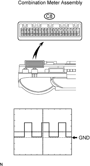 |
Check the output signal waveform.
Remove the combination meter, but do not disconnect the connector.
Using an oscilloscope, check the waveform of the combination meter.
| Item | Content |
| Tester Connection | C8-6 - C8-22 |
| Tool Setting | 5 V/DIV., 20 msec./DIV. |
| Vehicle Condition | Vehicle running |
| 3. CHECK TACHOMETER |
Check operation.
Connect a tune-up test tachometer, and start the engine.
Compare the tester tachometer values and vehicle tachometer values under the following conditions:
| Standard Tachometer Indication (rpm) | Acceptable Range (rpm) Data in ( ) are for reference only |
| 700 | 630 to 770 |
| 1,000 | (900 to 1100) |
| 2,000 | (1850 to 2150) |
| 3,000 | 2800 to 3200 |
| 4,000 | (3800 to 4200) |
| 5,000 | 4800 to 5200 |
| 4. CHECK FUEL SUCTION W/ PUMP AND GAUGE TUBE ASSEMBLY |
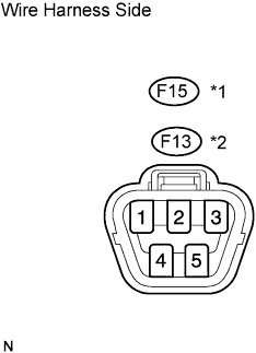 |
Disconnect the F15*1 or F13*2 pump and gauge connector.
Turn the ignition switch ON, and then check the position of the receiver gauge needle.
Connect terminals 2 and 3 of the wire harness side connector.
Turn the ignition switch ON, and then check the position of the receiver gauge needle.
| 5. CHECK FUEL LEVEL WARNING LIGHT |
Disconnect the F15*1 or F13*2 pump and gauge connector.
Turn the ignition switch ON, and then check that the fuel receiver gauge indicates E and that the fuel level warning light turns on.
| 6. CHECK LOW OIL PRESSURE WARNING LIGHT |
Disconnect the E4 switch connector.
Connect the E4-1 terminal of the wire harness side connector to the body ground.
Turn the ignition switch ON, and then check that the low oil pressure warning light turns on.
| 7. CHECK BRAKE WARNING LIGHT |
Check the parking brake warning light.
Disconnect the P2 switch connector.
Connect the P2-1 terminal of the wire harness side connector to the body ground.
Turn the ignition switch ON, and then check that the warning light turns on.
Check the brake fluid level warning light.
Disconnect the B2 switch connector.
Connect the B2-1 and B2-2 terminal of the wire harness side connector.
Turn the ignition switch ON, and then check that the warning light turns on.
1KD-FTV, 2KD-FTV:
Check the vacuum pump warning light.
Disconnect the B3 switch connector.
Connect the B3-1 terminal of the wire harness side connector to the body ground.
Turn the ignition switch ON, and then check that the warning light turns on.
| 8. CHECK SEAT BELT WARNING LIGHT FOR PASSENGER SIDE |
Disconnect the F11 switch connector.
Connect terminals 1 and 2 of the wire harness side connector.
Turn the ignition switch ON, and then check that the warning light blinks.
