METER / GAUGE SYSTEM > Warning Buzzer does not Sound |
| 1.INSPECT FUSE (TAIL) |
Remove the TAIL fuse from the instrument panel junction block (driver side junction block).
Measure the resistance of the fuse.
|
| ||||
| OK | |
| 2.CHECK COMBINATION METER BUZZER OPERATION |
Check the key reminder warning buzzer operation.
Turn the ignition switch OFF with the key inserted into the ignition key cylinder.
Open the driver side door.
Check the light reminder warning buzzer operation.
Turn the ignition switch OFF.
Set the light control switch to the TAIL or HEAD position.
Open the driver side door.
| Result | Proceed to |
| Key reminder warning buzzer does not sound | A |
| Light reminder warning buzzer does not sound | B |
|
| ||||
| A | |
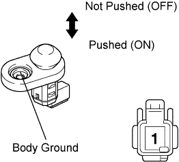
| 3.INSPECT UNLOCK WARNING SWITCH ASSEMBLY |
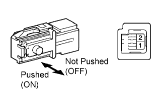 |
Remove the unlock warning switch.
Measure the resistance of the switch.
| Tester Connection | Condition | Specified Condition |
| 1 - 2 | Pushed (ON) | Below 1 Ω |
| 1 - 2 | Not pushed (OFF) | 10 kΩ or higher |
|
| ||||
| OK | |
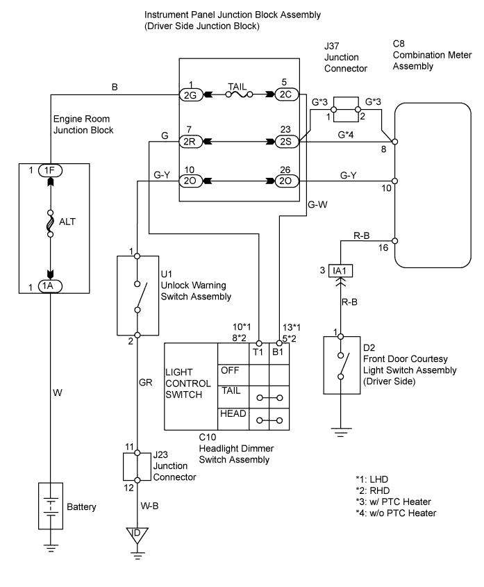
| 4.CHECK WIRE HARNESS (UNLOCK WARNING SWITCH - COMBINATION METER AND BODY GROUND) |
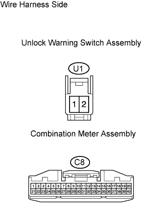 |
Disconnect the U1 switch connector.
Disconnect the C8 meter connector.
Measure the resistance of the wire harness side connectors.
| Tester Connection | Specified Condition |
| U1-1 - C8-10 | Below 1 Ω |
| U1-2 - Body ground | Below 1 Ω |
|
| ||||
| NG | ||
| ||
| 5.INSPECT HEADLIGHT DIMMER SWITCH ASSEMBLY |
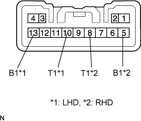 |
Remove the headlight dimmer switch.
Measure the resistance of the switch.
| Tester Connection | Switch Condition | Specified Condition |
| 13 (B1) - 10 (T1) | HEAD | Below 1 Ω |
| 13 (B1) - 10 (T1) | TAIL | Below 1 Ω |
| 13 (B1) - 10 (T1) | OFF | 10 kΩ or higher |
| Tester Connection | Switch Condition | Specified Condition |
| 5 (B1) - 8 (T1) | HEAD | Below 1 Ω |
| 5 (B1) - 8 (T1) | TAIL | Below 1 Ω |
| 5 (B1) - 8 (T1) | OFF | 10 kΩ or higher |
|
| ||||
| OK | |
| 6.CHECK WIRE HARNESS (HEADLIGHT DIMMER SWITCH - COMBINATION METER AND BATTERY) |
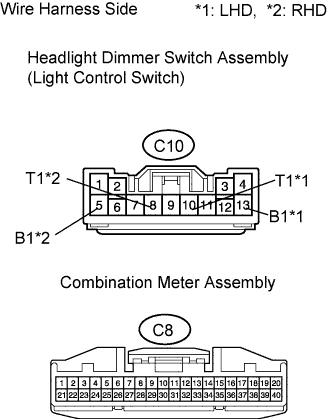 |
Disconnect the C10 switch connection.
Disconnect the C8 meter connection.
Measure the voltage of the wire harness side connectors.
| Tester Connection | Specified Condition |
| C10-13 (B1) - Body ground | 10 to 14 V |
| Tester Connection | Specified Condition |
| C10-5 (B1) - Body ground | 10 to 14 V |
Measure the resistance of the wire harness side connectors.
| Tester Connection | Specified Condition |
| C10-10 (T1) - C8-8 | Below 1 Ω |
| Tester Connection | Specified Condition |
| C10-8 (T1) - C8-8 | Below 1 Ω |
|
| ||||
| OK | |
| 7.INSPECT FRONT DOOR COURTESY LIGHT SWITCH ASSEMBLY (DRIVER SIDE) |
 |
Remove the courtesy light switch.
Measure the resistance of the switch.
| Tester Connection | Switch Condition | Specified Condition |
| 1 - Body ground | Not pushed (OFF) | Below 1 Ω |
| 1 - Body ground | Pushed (ON) | 10 kΩ or higher |
|
| ||||
| OK | |
| 8.CHECK WIRE HARNESS (FRONT DOOR COURTESY LIGHT SWITCH - COMBINATION METER) |
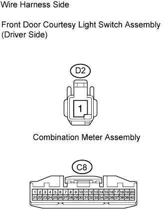 |
Disconnect the D2 switch connector.
Disconnect the C8 meter connector.
Measure the resistance of the wire harness side connectors.
| Tester Connection | Specified Condition |
| D2-1 - C8-16 | Below 1 Ω |
|
| ||||
| OK | ||
| ||
