METER / GAUGE SYSTEM > Seat Belt Warning Light for Passenger Seat does not Flash |
| 1.INSPECT FUSE (ECU-IG & GAUGE) |
Remove the ECU-IG & GAUGE fuse from the instrument panel junction block (driver side junction block).
Measure the resistance of the fuse.
|
| ||||
| OK | |
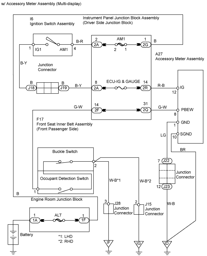
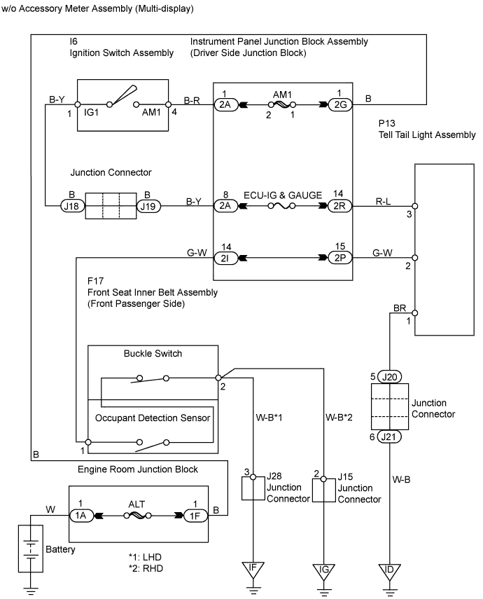
| 2.CHECK WIRE HARNESS (ACCESSORY METER*1 OR TELL TAIL LIGHT*2 - BATTERY AND GROUND) |
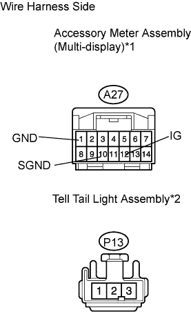 |
Disconnect the A27*1 meter connector.
Disconnect the P13*2 light connector.
Measure the voltage of the wire harness side connector.
| Tester Connection | Condition | Specified Condition |
| A27-12 (IG) - Body ground | Ignition switch ON | 10 to 14 V |
| A27-12 (IG) - Body ground | Ignition switch OFF | Below 1 V |
| Tester Connection | Condition | Specified Condition |
| P13-3 - Body ground | Ignition switch ON | 10 to 14 V |
| P13-3 - Body ground | Ignition switch OFF | Below 1 V |
Measure the resistance of the wire harness side connector.
| Tester Connection | Specified Condition |
| A27-1 (GND) - Body ground | Below 1 Ω |
| A27-10 (SGND) - Body ground | Below 1 Ω |
| Tester Connection | Specified Condition |
| P13-1 - Body ground | Below 1 Ω |
|
| ||||
| OK | |
| 3.INSPECT FRONT SEAT INNER BELT ASSEMBLY (PASSENGER SIDE) |
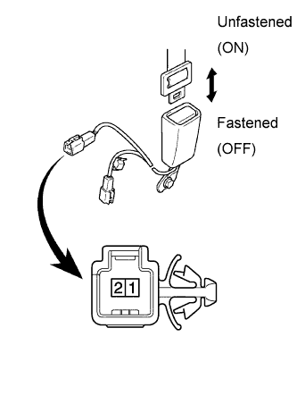 |
Disconnect the F17 belt connector.
Measure the resistance of the belt.
| Tester Connection | Condition | Specified Condition |
| 1 - 2 | Seat belt is unfastened (ON) | Below 100 Ω |
| 1 - 2 | Seat belt is fastened (OFF) | 1 MΩ or higher |
|
| ||||
| OK | |
| 4.CHECK WIRE HARNESS (FRONT SEAT INNER BELT ASSEMBLY - BODY GROUND) |
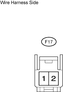 |
Disconnect the F17 belt connector.
Measure the resistance of the wire harness side connector.
| Tester Connection | Specified Condition |
| F17-2 - Body ground | Below 1 Ω |
|
| ||||
| OK | |
| 5.CHECK WIRE HARNESS (SEAT INNER BELT - ACCESSORY METER*1 OR TELL TAIL LIGHT*2) |
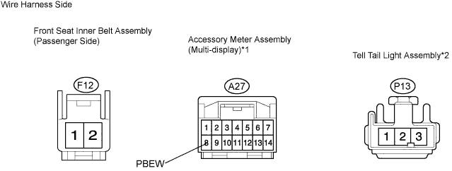
Disconnect the F17 belt connector.
Disconnect the A27*1 meter connector.
Disconnect the P13*2 light connector.
Measure the resistance of the wire harness side connectors.
| Tester Connection | Specified Condition |
| F17-1 - A27-8 (PBEW) | Below 1 Ω |
| Tester Connection | Specified Condition |
| F17-1 - P13-3 | Below 1 Ω |
| Result | Proceed to |
| OK (w/ Accessory meter assembly) | A |
| OK (w/o Accessory meter assembly) | B |
| NG | C |
|
| ||||
|
| ||||
| A | ||
| ||
| 6.INSPECT FRONT SEAT INNER BELT ASSEMBLY (OCCUPANT DETECTION SENSOR) |
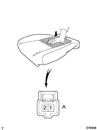 |
Disconnect the A sensor connector.
Measure the resistance of the sensor.
| Tester Connection | Condition | Specified Condition |
| 1 - 2 | Apply more than 147 N (15 kgf, 22 lbf) force to occupant detection sensor | Below 100 Ω |
| 1 - 2 | No force applied to occupant detection sensor | 1 MΩ or higher |
|
| ||||
| OK | ||
| ||
