METER / GAUGE SYSTEM > Malfunction in Fuel Receiver Gauge |
| 1.CHECK FUEL SUCTION W/ PUMP AND GAUGE TUBE ASSEMBLY |
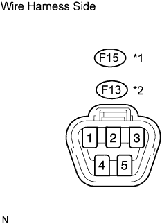 |
Disconnect the F15*1 or F13*2 pump and gauge connector.
Turn the ignition switch ON, and then check the position of the receiver gauge needle.
Connect terminals 2 and 3 on the wire harness side connector.
Turn the ignition switch ON, and then check the position of the receiver gauge needle.
|
| ||||
| OK | ||
| ||
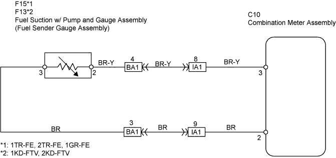
| 2.CHECK WIRE HARNESS (COMBINATION METER ASSEMBLY - FUEL SENDER GAUGE ASSEMBLY) |
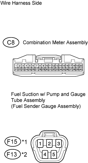 |
Disconnect the C8 meter connector.
Disconnect the F15*1 or F13*2 pump and gauge connector.
Measure the resistance of the wire harness side connectors.
| Tester Connection | Specified Condition |
| C8-2 - F15-3 | Below 1 Ω |
| C8-3 - F15-2 | Below 1 Ω |
| Tester Connection | Specified Condition |
| C8-2 - F13-3 | Below 1 Ω |
| C8-3 - F13-2 | Below 1 Ω |
|
| ||||
| OK | ||
| ||
