METER / GAUGE SYSTEM > Malfunction in Speedometer |
| 1.INSPECT FUSE (ECU-IG & GAUGE) |
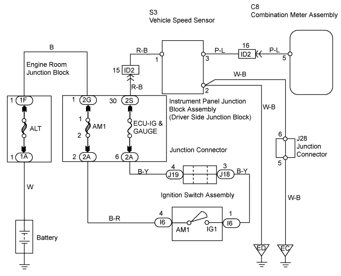
Remove the ECU-IG & GAUGE fuse from the instrument panel junction block (driver side junction block).
Measure the resistance of the fuse.
|
| ||||
| OK | |
| 2.INSPECT VEHICLE SPEED SENSOR |
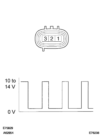 |
Measure the voltage of the sensor.
| Tester Connection | Condition | Specified Condition |
| 2 - 3 |
| 10 to 14 V (Pulse generation) |
|
| ||||
| OK | |
| 3.CHECK COMBINATION METER ASSEMBLY |
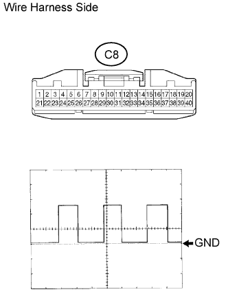 |
Disconnect the C8 meter connector.
Using an oscilloscope, check the signal waveform of the meter.
| Tester Connection | Tool Setting | Vehicle Condition |
| C8-5 - Body ground | 5 V/DIV., 20 msec./DIV. | Drive vehicle at 20 km/h (12 mph) |
|
| ||||
| OK | ||
| ||
| 4.CHECK WIRE HARNESS (VEHICLE SPEED SENSOR - BATTERY AND BODY GROUND) |
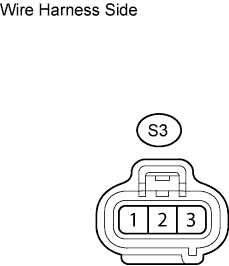 |
Disconnect the S3 sensor connector.
Measure the voltage of the wire harness side connector.
| Tester Connection | Condition | Specified Condition |
| S3-1 - Body ground | Ignition switch ON | 10 to 14 V |
| S3-1 - Body ground | Ignition switch OFF | Below 1 V |
Measure the resistance of the wire harness side connector.
| Tester Connection | Specified Condition |
| S3-2 - Body ground | Below 1 Ω |
|
| ||||
| OK | |
| 5.CHECK WIRE HARNESS (VEHICLE SPEED SENSOR - COMBINATION METER ASSEMBLY) |
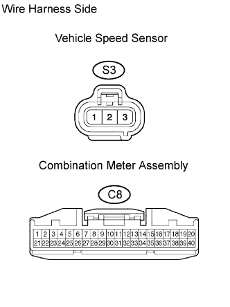 |
Disconnect the S3 sensor connector.
Disconnect the C8 meter connector.
Measure the resistance of the wire harness side connectors.
| Tester Connection | Specified Condition |
| S3-3 - C8-5 | Below 1 Ω |
|
| ||||
| OK | ||
| ||
