METER / GAUGE SYSTEM > Entire Combination Meter does not Operate |
| 1.INSPECT FUSE (DCC, DOME, MET) |
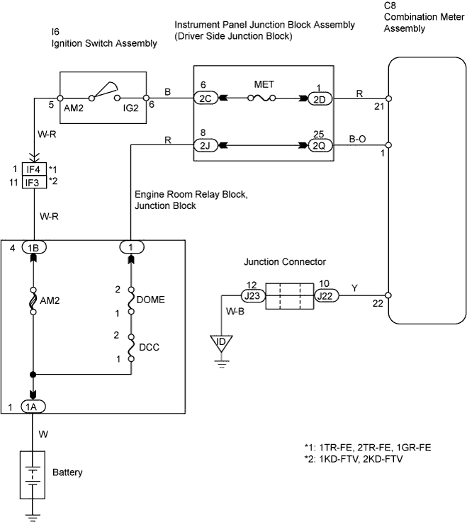
Remove the DCC and DOME fuses from the engine room junction block.
Remove the MET fuse from the instrument panel junction block (driver side junction block).
Measure the resistance of the fuses.
|
| ||||
| OK | |
| 2.CHECK WIRE HARNESS (COMBINATION METER ASSEMBLY - BATTERY AND BODY GROUND) |
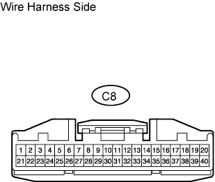 |
Disconnect the C8 meter connector.
Measure the voltage of the wire harness side connector.
| Tester Connection | Condition | Specified Condition |
| C8-1 - Body ground | Always | 10 to 14 V |
| C8-21 - Body ground | Ignition switch ON | 10 to 14 V |
| C8-21 - Body ground | Ignition switch OFF | Below 1 V |
Measure the resistance of the wire harness side connector.
| Tester Connection | Specified Condition |
| C8-22 - Body ground | Below 1 Ω |
|
| ||||
| OK | ||
| ||
