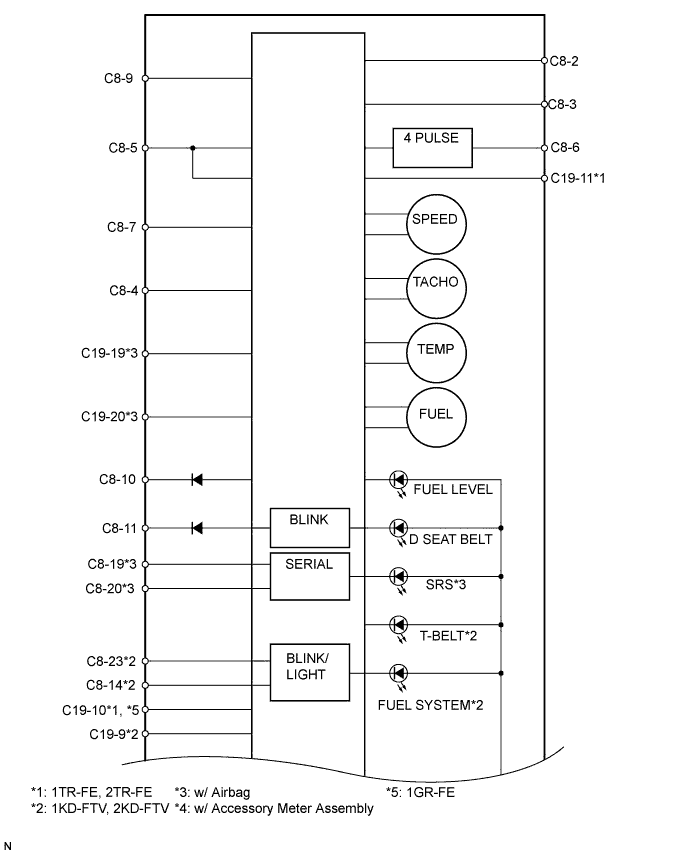
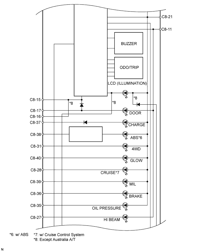
METER / GAUGE SYSTEM > TERMINALS OF ECU |
| CHECK COMBINATION METER ASSEMBLY |
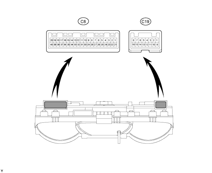
Disconnect the C8 and C19 meter connectors.
Measure the resistance of the wire harness side connectors.
| Terminal No. | Wiring Color | Terminal Description | Condition | Specified Condition |
| C8-1 - Body ground | R - Body ground | Battery | Always | 10 to 14 V |
| C8-21 - C8-22 | B-O - Y | IG2 signal | Ignition switch ON | 10 to 14 V |
| C8-21 - C8-22 | B-O - Y | IG2 signal | Ignition switch OFF | Below 1 V |
| C19-11 - Body ground*1 | B-R - Body ground | Power supply for fuel consumption calculation | Ignition switch ON | 10 to 14 V |
| C19-11 - Body ground*1 | B-R - Body ground | Power supply for fuel consumption calculation | Ignition switch OFF | Below 1 V |
| C8-22 - Body ground | Y - Body ground | Ground | Always | Below 1 Ω |
| C8-19 - Body ground*2 | W-B - Body ground | Ground | Always | Below 1 Ω |
| C8-38 - Body ground*3 | R-G - Body ground | Ground | Always | Below 1 Ω |
| C8-9 - Body ground*4 | W-G - Body ground | Ground | Always | Below 1 Ω |
| C8-9 - Body ground*5 | W-G - Body ground | Rheostat signal | Rheostat knob fully turned to left position | 702 Ω |
| C8-9 - Body ground*5 | W-G - Body ground | Rheostat signal | Rheostat knob fully turned to right position | Below 1 Ω |
Reconnect the C8 and C19 meter connectors.
Measure the voltage of the connectors.
| Terminal No. | Wiring Color | Terminal Description | Condition | Specified Condition |
| C8-2 - C8-3 | BR - BR-Y | Fuel level signal | Ignition switch ON, fuel level F | Below 1 V |
| C8-2 - C8-3 | BR - BR-Y | Fuel level signal | Ignition switch ON, fuel level F | 4 to 7 V |
| C8-5 - Body ground | P-L - Body ground | Vehicle speed signal (input) | Ignition switch ON, slowly turn wheel | Pulse generation (see waveform 1) |
| C8-6 - Body ground | V-R - Body ground | Vehicle speed signal (output) | Vehicle is driven | Pulse generation (see waveform 1) |
| C8-7 - Body ground | B-W - Body ground | Tachometer signal | Engine running | Pulse generation (see waveform 2) |
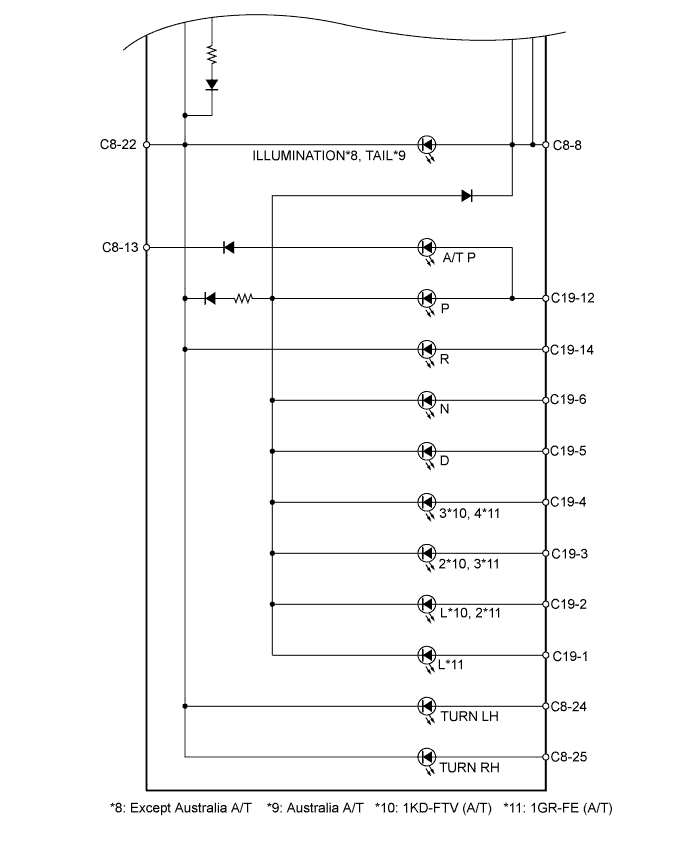
| C8-8 - C8-22 | G - Y | Light control switch signal | Light control switch is OFF | Below 1 V |
| C8-8 - C8-22 | G - Y | Light control switch signal | Light control switch is ON | 10 to 14 V |
| C8-10 - Body ground | G-Y - Body ground | Unlock warning switch signal | No key in ignition key cylinder | Below 1 V |
| C8-10 - Body ground | G-Y - Body ground | Unlock warning switch signal | Ignition switch OFF, key is in ignition key cylinder | 10 to 14 V |
| C8-11 - Body ground | R-Y - Body ground | Driver side seat belt warning signal | Ignition switch ON, driver side seat belt unfastened | Below 1 V |
| C8-11 - Body ground | R-Y - Body ground | Driver side seat belt warning signal | Ignition switch ON, driver side seat belt fastened | 10 to 14 V |
| C8-12 - C8-13*1 | G-B - W-G | Unengaged park warning signal | Ignition switch ON, A/T shift lever on P, transfer shift lever not on P | 10 to 14 V |
| C8-12 - C8-13*1 | G-B - W-G | Unengaged park warning signal | Ignition switch ON, A/T shift lever on P, transfer shift lever on P | Below 1 V |
| C8-14 - Body ground*3 | W-G - Body ground | Fuel filter warning signal | Ignition switch ON, fuel system warning light OFF | Below 1 V |
| C8-14 - Body ground*3 | W-G - Body ground | Fuel filter warning signal | Ignition switch ON, fuel system warning light ON | 10 to 14 V |
| C8-15 - Body ground | R-B - Body ground | Driver side door signal (output) | Driver side door is closed | Below 1 V |
| C8-15 - Body ground | R-B - Body ground | Driver side door signal (output) | Driver side door is open | 10 to 14 V |
| C8-16 - Body ground | R-B - Body ground | Driver side door signal (input) | Driver side door is closed | Below 1 V |
| C8-16 - Body ground | R-B - Body ground | Driver side door signal (input) | Driver side door is open | Below 1 V |
| C8-17 - Body ground | R-L - Body ground | Door signal | All doors are closed | 10 to 14 V |
| C8-17 - Body ground | R-L - Body ground | Door signal | All doors are open | Below 1 V |
| C8-18 - Body ground*1 | P - Body ground | ATF temperature warning signal | Ignition switch ON, ATF temperature warning light OFF | 10 to 14 V |
| C8-18 - Body ground*1 | P - Body ground | ATF temperature warning signal | Ignition switch ON, ATF temperature warning light ON | Below 1 V |
| C8-23 - Body ground*3 | L-R - Body ground | Sedimenter warning signal | Ignition switch ON, fuel system warning light OFF | 10 to 14 V |
| C8-23 - Body ground*3 | L-R - Body ground | Sedimenter warning signal | Ignition switch ON, fuel system warning light ON | Below 1 V |
| C8-24 - C8-22 | G-B - Y | Turn signal indicator LH signal | Ignition switch ON, turn signal indicator LH light OFF | Below 1 V |
| C8-24 - C8-22 | G-B - Y | Turn signal indicator LH signal | Ignition switch ON, turn signal indicator LH light ON | 10 to 14 V |
| C8-25 - C8-22 | G-Y - Y | Turn signal indicator RH signal | Ignition switch ON, turn signal indicator RH light OFF | Below 1 V |
| C8-25 - C8-22 | G-Y - Y | Turn signal indicator RH signal | Ignition switch ON, turn signal indicator RH light ON | 10 to 14 V |
| C8-27 - Body ground | R-Y - Body ground | HI BEAM indicator signal | HI BEAM indicator light OFF | 10 to 14 V |
| C8-27 - Body ground | R-Y - Body ground | HI BEAM indicator signal | HI BEAM indicator light ON | Below 1 V |
| C8-28 - Body ground*4 | L-B - Body ground | Cruise indicator signal | Ignition switch ON, cruise control main switch OFF | 10 to 14 V |
| C8-28 - Body ground*4 | L-B - Body ground | Cruise indicator signal | Ignition switch ON, cruise control main switch ON | Below 1 V |
| C8-31 - Body ground*4 | R-B - Body ground | 4WD indicator signal | Ignition switch ON, transfer shift lever in position other than H4 or L4 | 10 to 14 V |
| C8-31 - Body ground*4 | R-B - Body ground | 4WD indicator signal | Ignition switch ON, transfer shift lever on H4 or L4 | Below 1 V |
| C8-35 - Body ground | LG-B - Body ground | Oil pressure warning signal | Ignition switch ON, oil pressure warning light OFF | 10 to 14 V |
| C8-35 - Body ground | LG-B - Body ground | Oil pressure warning signal | Ignition switch ON, oil pressure warning light ON | Below 1 V |
| C8-36 - Body ground | LG - Body ground | Brake warning signal | Ignition switch ON, brake warning light OFF | 10 to 14 V |
| C8-36 - Body ground | LG - Body ground | Brake warning signal | Ignition switch ON, brake warning light ON | Below 1 V |
| C8-37 - Body ground | GR - Body ground | Charge warning signal | Ignition switch ON, charge warning light OFF | 10 to 14 V |
| C8-37 - Body ground | GR - Body ground | Charge warning indicator | Ignition switch ON, charge warning light ON | Below 1 V |
| C8-38 - Body ground*2 | R-G - Body ground | ABS warning indicator | Ignition switch ON, ABS warning light OFF | 10 to 14 V |
| C8-38 - Body ground*2 | R-G - Body ground | ABS warning signal | Ignition switch ON, ABS warning light ON | Below 1 V |
| C8-39 - Body ground | R-B - Body ground | MIL signal | Ignition switch ON, MIL warning light OFF | 10 to 14 V |
| C8-39 - Body ground | R-B - Body ground | MIL signal | Ignition switch ON, MIL warning light ON | Below 1 V |
| C8-40 - Body ground*3 | Y-R - Body ground | Glow indicator signal | Ignition switch ON, Glow indicator light OFF | 10 to 14 V |
| C8-40 - Body ground*3 | Y-R - Body ground | Glow indicator signal | Ignition switch ON, Glow indicator light ON | Below 1 V |
| C19-1 - Body ground*5 | GR-L - Body ground | A/T shift position signal (L) | Ignition switch ON, A/T L indicator light OFF | Below 1 V |
| C19-1 - Body ground*5 | GR-L - Body ground | A/T shift position signal (L) | Ignition switch ON, A/T L indicator light ON | 10 to 14 V |
| C19-2 - Body ground*5 | G-R - Body ground | A/T shift position signal (L) | Ignition switch ON, A/T L indicator light OFF | Below 1 V |
| C19-2 - Body ground*5 | G-R - Body ground | A/T shift position signal (L) | Ignition switch ON, A/T L indicator light ON | 10 to 14 V |
| C19-2 - Body ground*5 | P-L - Body ground | A/T shift position signal (2) | Ignition switch ON, A/T 2 indicator light OFF | Below 1 V |
| C19-2 - Body ground*5 | P-L - Body ground | A/T shift position signal (2) | Ignition switch ON, A/T 2 indicator light ON | 10 to 14 V |
| C19-3 - Body ground*5 | L - Body ground | A/T shift position signal (2) | Ignition switch ON, A/T 2 indicator light OFF | Below 1 V |
| C19-3 - Body ground*5 | L - Body ground | A/T shift position signal (2) | Ignition switch ON, A/T 2 indicator light ON | 10 to 14 V |
| C19-3 - Body ground*5 | L - Body ground | A/T shift position signal (3) | Ignition switch ON, A/T 3 indicator light OFF | Below 1 V |
| C19-3 - Body ground*5 | L - Body ground | A/T shift position signal (3) | Ignition switch ON, A/T 3 indicator light ON | 10 to 14 V |
| C19-4 - Body ground*5 | G-O - Body ground | A/T shift position signal (3) | Ignition switch ON, A/T 3 indicator light OFF | Below 1 V |
| C19-4 - Body ground*5 | G-O - Body ground | A/T shift position signal (3) | Ignition switch ON, A/T 3 indicator light ON | 10 to 14 V |
| C19-4 - Body ground*5 | G-O - Body ground | A/T shift position signal (4) | Ignition switch ON, A/T 4 indicator light OFF | Below 1 V |
| C19-4 - Body ground*5 | G-O - Body ground | A/T shift position signal (4) | Ignition switch ON, A/T 4 indicator light ON | 10 to 14 V |
| C19-5 - Body ground*6 | B-R - Body ground | A/T shift position signal (D) | Ignition switch ON, A/T D indicator light OFF | Below 1 V |
| C19-5 - Body ground*6 | B-R - Body ground | A/T shift position signal (D) | Ignition switch ON, A/T D indicator light ON | 10 to 14 V |
| C19-6 - Body ground*6 | R-W - Body ground | A/T shift position signal (N) | Ignition switch ON, A/T N indicator light OFF | Below 1 V |
| C19-6 - Body ground*6 | R-W - Body ground | A/T shift position signal (N) | Ignition switch ON, A/T N indicator light ON | 10 to 14 V |
| C19-9 - Body ground*3 | G-B - Body ground | Signal for amount of fuel consumption | Engine running | Pulse generation |
| C19-10 - Body ground*7 | L - Body ground | Injector signal | Engine running | Pulse generation |
| C19-14 - Body ground*6 | R-Y - Body ground | A/T shift position signal (R) | Ignition switch ON, A/T L indicator light OFF | Below 1 V |
| C19-14 - Body ground*6 | R-Y - Body ground | A/T shift position signal (R) | Ignition switch ON, A/T R indicator light ON | 10 to 14 V |
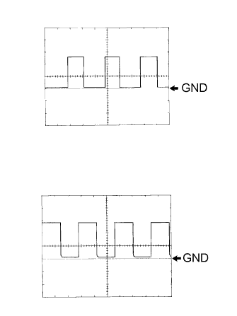 |
Using an oscilloscope, check the signal waveform of the meter.
| Item | Content |
| Terminal No. | C8-5 - Body ground |
| Tool Setting | 5 V/DIV., 10 msec./DIV. |
| Vehicle Condition | Driving at approx. 20 km/h (12 mph) |
| Item | Content |
| Terminal No. | C8-7 - Body ground |
| Tool Setting | 5 V/DIV., 10 msec./DIV. |
| Vehicle Condition | Engine idling |
| CHECK ACCESSORY METER (MULTI-DISPLAY) |

Disconnect the A27 meter connector.
Measure the voltage and resistance of the wire harness side connector.
| Symbols (Terminal No.) | Wiring Color | Terminal Description | Condition | Specified Condition |
| +B (A27-14) - Body ground | R - Body ground | +B power supply | Always | 10 to 14 V |
| IG (A27-12) - Body ground | R-B - Body ground | IG power supply | Ignition switch ON | 10 to 14 V |
| IG (A27-12) - Body ground | R-B - Body ground | IG power supply | Ignition switch OFF | Below 1 V |
| ACC (A27-13) - Body ground | G-R - Body ground | ACC power supply | Ignition switch ACC | 10 to 14 V |
| ACC (A27-13) - Body ground | G-R - Body ground | ACC power supply | Ignition switch OFF | Below 1 V |
| GND1 (A27-1) - Body ground | LG - Body ground | Ground | Always | Below 1 Ω |
| SGND (A27-10) - Body ground | BR - Body ground | Ground | Always | Below 1 Ω |
Reconnect the A27 meter connector.
Measure the voltage of the connector.
| Symbols (Terminal No.) | Wiring Color | Terminal Description | Condition | Specified Condition |
| SG (A27-2) - TH+ (A27-3) | BR-Y - W-G | A/C ambient temperature sensor signal | Ignition switch ON, ambient temperature 25 °C (77 °F) | 1.35 to 1.75 V |
| SG (A27-2) - TH+ (A27-3) | BR-Y - W-G | A/C ambient temperature sensor signal | Ignition switch ON, ambient temperature 40°C (104 °F) | 0.85 to 2.34 V |
| Terminal No. | Wire Harness Side | |
| C8 | 1 | DOME Fuse |
| 2 | Fuel Suction w/ Pump and Gauge Tube Assembly | |
| 3 | Fuel Suction w/ Pump and Gauge Tube Assembly | |
| 4 | ECM | |
| 5 | Vehicle Speed Sensor | |
| 6 | 4 Pulse Output | |
| 7 | ECM | |
| 8 | Headlight Dimmer Switch Assembly | |
| 9 | Light Control Rheostat | |
| 10 | Unlock Warning Switch Assembly | |
| 11 | Front Seat Inner Belt Assembly (Driver Side) | |
| 12 | PNP Switch Assembly*1 | |
| 13 | Transfer Neutral Detection Switch*1 | |
| 14 | Fuel Filter Assembly (Fuel Filter Switch)*2 | |
| 15 | Integration Relay | |
| 16 | Front Door Courtesy Light Switch Assembly (Driver Side) | |
| 17 | Door Courtesy Light Switch Assembly | |
| 18 | TCM*3 | |
| 19 | Body ground*4 | |
| 20 | Center Airbag Sensor Assembly*5 | |
| 21 | MET Fuse | |
| 22 | Body ground | |
| 23 | Fuel Filter (Fuel Sedimenter Switch)*2 | |
| 24 | Turn Signal Flasher Relay | |
| 25 | Turn Signal Flasher Relay | |
| 26 | - | |
| 27 | Headlight Dimmer Switch Assembly | |
| 28 | ECM (CRUISE)*6 | |
| 29 | - | |
| 30 | - | |
| 31 | 4WD Control ECU*7 | |
| 32 | - | |
| 33 | - | |
| 34 | - | |
| 35 | Oil Pressure Switch Assembly | |
| 36 | Parking Brake Switch Assembly Brake Fluid Level Warning Switch Vacuum Warning Switch | |
| 37 | Generator Assembly | |
| 38 | Skid Control ECU with Actuator*5, Body Ground*5 | |
| 39 | ECM (MIL) | |
| 40 | ECM (GLOW)*2 | |
| Terminal No. | Wire Harness Side | |
| C19 | 1 | PNP Switch*1 |
| 2 | PNP Switch*2 Shift Lock Control ECU*3 | |
| 3 | PNP Switch*1 | |
| 4 | Shift Lock Control ECU*1 | |
| 5 | Shift Lock Control ECU*1 | |
| 6 | PNP Switch*1 | |
| 7 | - | |
| 8 | - | |
| 9 | ECM*4 | |
| 10 | Fuel Injector Assembly*5 | |
| 11 | INJ Fuse*6 | |
| 12 | Accessory Meter Assembly (Multi-display)*7 | |
| 13 | Accessory Meter Assembly (Multi-display)*7 | |
| 14 | PNP Switch*1 | |
| 15 | - | |
| 16 | - | |
