DTC C1241/41 Low Battery Positive Voltage or Abnormally High Battery Positive Voltage |
| DTC No. | DTC Detection Condition | Trouble Area |
| C1241/41 | When either of following is detected: 1. Both conditions continue for at least 10 seconds
|
|
| 1.INSPECT FUSE (ECU-IG & GAUGE) |
Remove the ECU-IG & GAUGE fuse from the instrument panel J/B.
Measure the resistance of the fuse.
|
| ||||
| OK | |
| 2.INSPECT BATTERY |
Check the battery voltage.
| Result | Proceed to |
| Battery voltage is normal (when using intelligent tester) | A |
| Battery voltage is normal (when not using intelligent tester) | B |
| Battery voltage is abnormal | C |
|
| ||||
|
| ||||
| A | |
| 3.READ DATA LIST (ECU IG POWER VOLTAGE) |
Using the Data List, check for proper functioning of the ECU IG power voltage.
| Item | Measurement Item / Range (Display) | Normal Condition | Diagnostic Note |
| ECU IG Power Voltage | ECU power supply voltage / TOO LOW / NORMAL / TOO HIGH | TOO HIGH: more than 14.0 V NORMAL: 10 to 14.0 V TOO LOW: Below 10 V | - |
| Result | Proceed to |
| Display is NORMAL | A |
| Display is not NORMAL | B |
|
| ||||
| A | ||
| ||
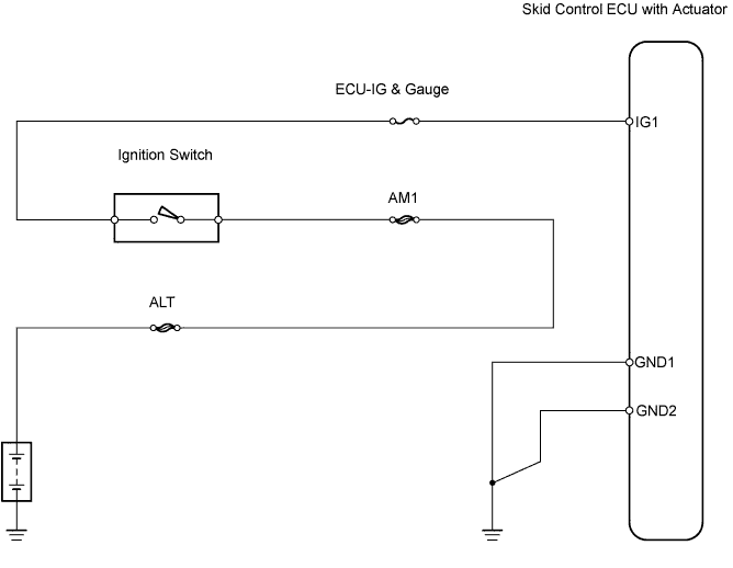
| 4.CHECK WIRE HARNESS (SKID CONTROL ECU - BATTERY) |
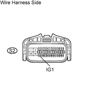 |
Disconnect the S2 ECU connector.
Turn the ignition switch ON.
Measure the voltage of the wire harness side connector.
| Tester Connection | Specified Condition |
| S2-25 (IG1) - Body ground | 10 to 14 V |
|
| ||||
| OK | |
| 5.CHECK WIRE HARNESS (SKID CONTROL ECU - BODY GROUND) |
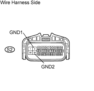 |
Disconnect the S2 ECU connector.
Measure the resistance of the wire harness side connector.
| Tester Connection | Specified Condition |
| S2-2 (GND1) - Body ground | Below 1 Ω |
| S2-24 (GND2) - Body ground | Below 1 Ω |
|
| ||||
| OK | |
| 6.CHECK IF DTC OUTPUT RECURS |
Clear the DTCs.
Drive the vehicle at approximately 30 km/h (19 mph) or more for 60 seconds or more.
Check for DTCs.
| Result | Proceed to |
| DTC is output | A |
| DTC is not output | B |
|
| ||||
| A | ||
| ||
