MANUAL TRANSMISSION ASSEMBLY > INSTALLATION |
| 1. INSTALL MANUAL TRANSMISSION UNIT ASSEMBLY |
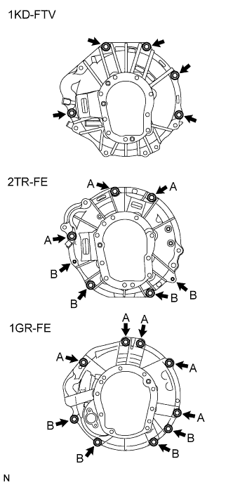 |
Align the input shaft with the clutch disc and install the transmission to the engine.
1KD-FTV:
Install the 5 bolts.
2TR-FE:
Install the 7 bolts.
1GR-FE:
Install the 9 bolts.
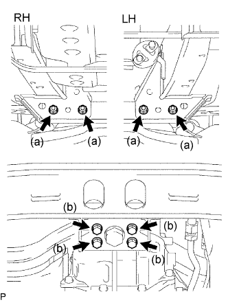
| 2. INSTALL STIFFENER PLATE (1KD-FTV) |
 |
Install the stiffener pate RH with the 4 bolts.
Install the stiffener pate LH with the 4 bolts.
| 3. INSTALL EXHAUST MANIFOLD STAY (for 2TR-FE) |
 |
Install the exhaust manifold stay with the 3 bolts.
| 4. INSTALL REAR NO. 1 ENGINE MOUNTING INSULATOR |
 |
Install the mounting insulator with the 4 bolts.
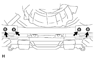
| 5. INSTALL NO. 3 FRAME CROSSMEMBER SUB-ASSEMBLY |
 |
Install the frame crossmember with the 4 bolts and 4 nuts.
Install the 4 set bolts to the No. 1 engine mounting insulator rear.
| 6. INSTALL STARTER ASSEMBLY |
Install the starter assembly.
For 1KD-FTV (Click here)
For 2TR-FE (Click here)
For 1GR-FE (Click here)
| 7. CONNECT CLUTCH RELEASE CYLINDER ASSEMBLY (for 1KD-FTV, 2TR-FE) |
 |
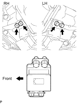
Install the clutch release cylinder with the 2 bolts.
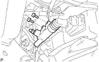
| 8. CONNECT CLUTCH RELEASE CYLINDER ASSEMBLY (1GR-FE) |
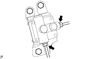 |
Install the accumulator with the 3 bolts.
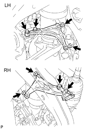
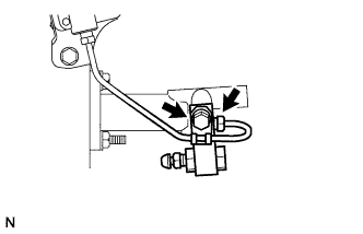
Using SST, connect the 2 flexible hose tubes.
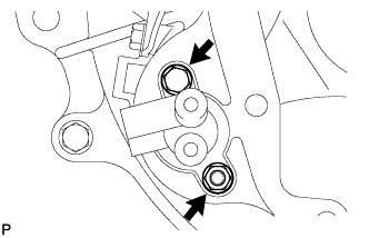 |
Install the clutch release cylinder assembly with the 2 bolts.
 |
Using SST, connect the flexible tube.
Install the 2 way with the bolt.
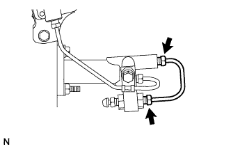 |
Using SST, connect the flexible tube.
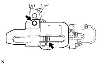 |
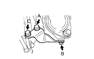
Install the release cylinder heat insulator with the bolt and nut.
| 9. CONNECT WIRE HARNESS |
Connect the back-up light switch connector and speedometer sensor connector.
| 10. INSTALL FRONT EXHAUST PIPE ASSEMBLY |
Install the front exhaust pipe assembly.
For 1KD-FTV (Click here)
For 2TR-FE (Click here)
For 1GR-FE (Click here)
| 11. INSTALL REAR PROPELLER SHAFT ASSEMBLY |
Install the rear propeller shaft assembly (Click here).
| 12. INSTALL NO. 2 FRAME CROSSMEMBER SUB-ASSEMBLY |
 |
Install the frame crossmember with the 4 bolts and 4 nuts.
| 13. ADD MANUAL TRANSMISSION OIL |
 |
| 14. INSTALL FLOOR SHIFT SHIFT LEVER ASSEMBLY |
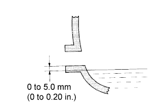
Cover the shift lever cap with a cloth.
Press down on the shift lever cap and rotate it clockwise to install it.
| 15. INSTALL SHIFT LEVER BOOT ASSEMBLY |
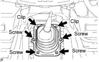 |
Install the shift lever boot with the 4 screws and 2 clips.
| 16. INSTALL CONSOLE BOX ASSEMBLY |
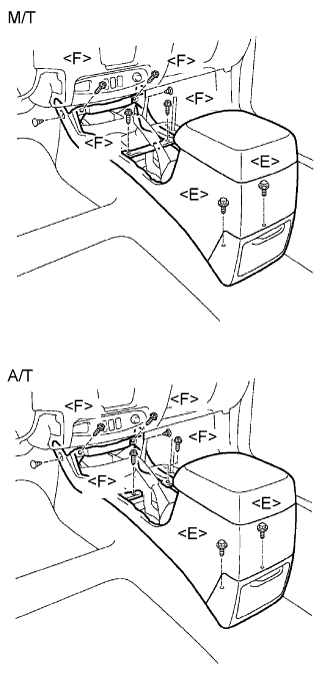 |
Install the console box with the 2 clips, 4 screws <F> and 2 bolts <E>.
| 17. INSTALL UPPER CONSOLE PANEL ASSEMBLY |
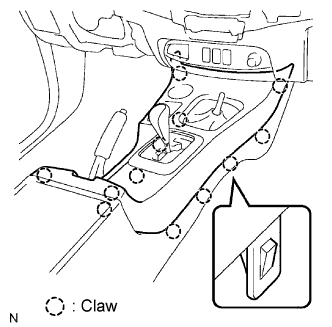 |
Attach the 12 claws to install the console panel.
| 18. INSTALL SHIFT LEVER KNOB SUB-ASSEMBLY |
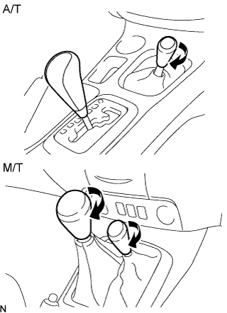 |
w/ M/T:
Twist the knob in the direction indicated by the arrow to install it.
w/ 4WD:
Twist the transfer shift lever knob in the direction indicated by the arrow to install it.
| 19. CONNECT CABLE TO NEGATIVE BATTERY TERMINAL |
| 20. PERFORM INITIALIZATION |
Perform initialization (Click here).
| 21. CHECK SRS WARNING LIGHT |
Check the SRS warning light (Click here).
| 22. BLEED AIR FROM CLUTCH PIPE LINE (1GR-FE) |
Bleed air from the clutch system.
Fill the master cylinder reservoir with fluid.
| 23. CHECK FOR CLUTCH FLUID LEAKAGE (1GR-FE) |
Check for clutch fluid leakage (Click here).
| 24. INSPECT AND ADJUST CLUTCH PEDAL ASSEMBLY (1GR-FE) |
Inspect and adjust clutch pedal assembly.
For LHD (Click here)
For RHD (Click here)
| 25. CHECK FOR FLUID LEVEL IN RESERVOIR (1GR-FE) |
Check for fluid level in reservoir (Click here).
