OUTPUT SHAFT > REMOVAL |
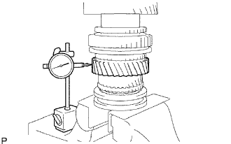
| 1. INSPECT 1ST GEAR THRUST CLEARANCE |
 |
Using a dial indicator, measure the thrust clearance.
| 2. INSPECT 2ND GEAR THRUST CLEARANCE |
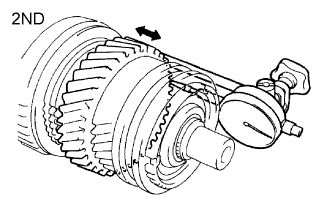 |
Using a dial indicator, measure the thrust clearance.
| 3. INSPECT 3RD GEAR THRUST CLEARANCE |
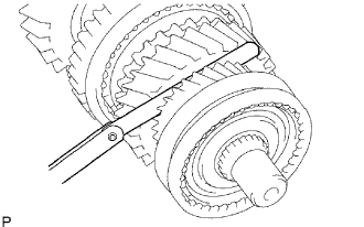 |
Using a feeler gauge, measure the thrust clearance.
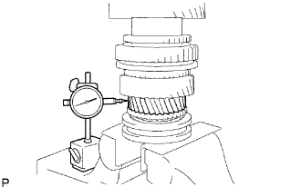
| 4. INSPECT 1ST GEAR RADIAL CLEARANCE |
 |
Using a dial indicator, measure the radial clearance.
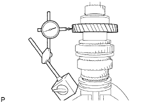
| 5. INSPECT 2ND GEAR RADIAL CLEARANCE |
 |
Using a dial indicator, measure the radial clearance.
| 6. INSPECT 3RD GEAR RADIAL CLEARANCE |
 |
Using a dial indicator, measure the radial clearance.
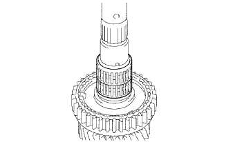
| 7. REMOVE 1ST GEAR |
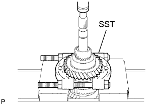 |
Using SST and a press, press out the 5 the gear, the output shaft center bearing, the 1st gear thrust washer and the 1st gear from the output shaft.
| 8. REMOVE NO. 1 SYNCHRONIZER RING SET (FOR 1ST GEAR) |
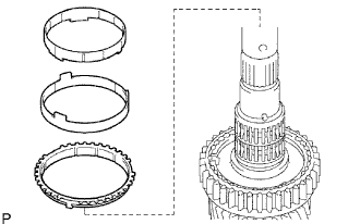 |
Remove synchronizer ring (for 1st gear) from the output shaft.
| 9. REMOVE 1ST GEAR THRUST WASHER PIN |
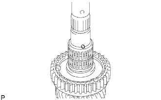 |
Remove the thrust washer pin from the output shaft.
| 10. REMOVE 1ST GEAR NEEDLE ROLLER BEARING |
 |
Remove the needle roller bearing from the output shaft.
| 11. REMOVE 1ST GEAR BEARING SPACER |
 |
Remove the bearing spacer from the output shaft.
| 12. REMOVE BEARING SHAFT SNAP RING |
 |
Using 2 screwdrivers and a hammer, tap out the snap ring from the output shaft.
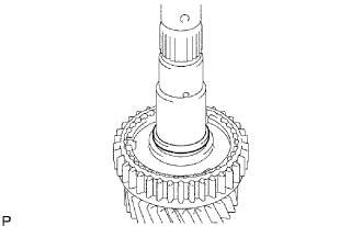
| 13. REMOVE 2ND GEAR |
 |
Using SST and a press, press out the No. 1 transmission clutch hub with the reverse gear, No. 1 synchronizer ring set and 2nd gear from the output shaft.
| 14. REMOVE 2ND GEAR NEEDLE ROLLER BEARING |
 |
Remove the needle roller bearing from the output shaft.
| 15. REMOVE REVERSE GEAR |
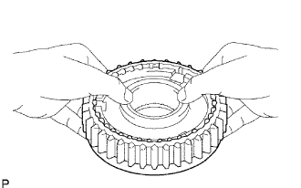 |
Remove the reverse gear, 3 No. 1 synchromesh shifting keys, and 3 synchromesh shifting key springs.
| 16. REMOVE CLUTCH HUB SET SHAFT SNAP RING |
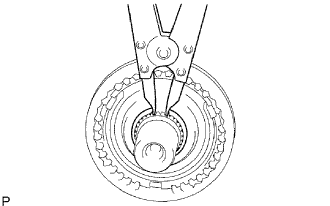 |
Using a snap ring expander, remove the snap ring from the output shaft.
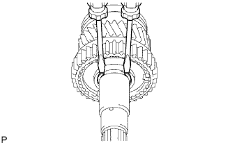
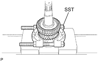
| 17. REMOVE 3RD GEAR |
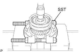 |
Using SST and a press, press out the No. 2 transmission clutch hub with the No. 2 transmission hub sleeve, No. 2 synchronizer ring and 3rd gear from the output shaft.
| 18. REMOVE 3RD GEAR NEEDLE ROLLER BEARING |
 |
Remove the needle roller bearing from the output shaft.
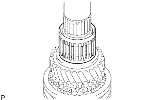
| 19. REMOVE NO. 2 TRANSMISSION HUB SLEEVE |
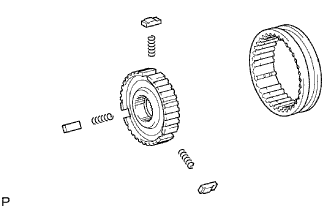 |
Remove the No. 2 hub sleeve, 3 No. 2 synchromesh shifting key springs, and 3 No. 2 synchromesh shifting keys from the No. 2 clutch hub.
| 20. INSPECT OUTPUT SHAFT |
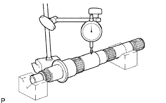 |
Using a dial indicator, measure the output shaft runout.
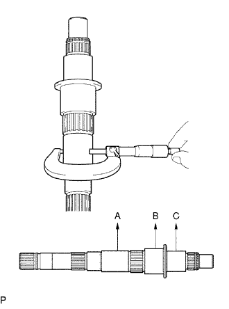 |
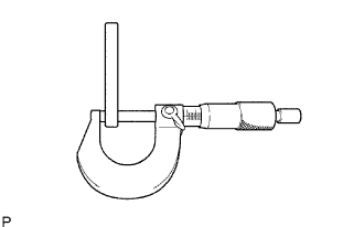
Using a micrometer, measure the outside diameter at A, B and C on the output shaft.
| Mark | Outside Diameter |
| A | 38.979 to 38.995 mm (1.5334 to 1.5352 in.) |
| B | 46.984 to 47.000 mm (1.8498 to 1.8504 in.) |
| C | 37.984 to 38.000 mm (1.4954 to 1.4961 in.) |
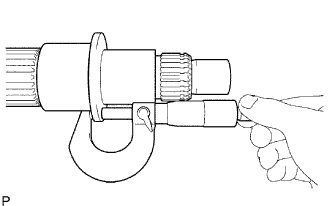 |
Using a micrometer, measure the thickness of the output shaft flange as shown in the illustration.
| 21. INSPECT 3RD GEAR |
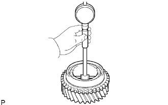 |
Using a cylinder gauge, measure the inside diameter of the 3rd gear.
| 22. INSPECT 2ND GEAR |
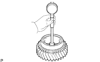 |
Using a cylinder gauge, measure the inside diameter of the 2nd gear.
| 23. INSPECT 1ST GEAR |
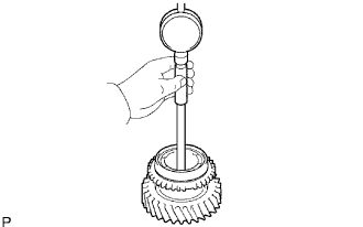 |
Using a cylinder gauge, measure the inside diameter of the 1st gear.
| 24. INSPECT 1ST GEAR THRUST WASHER |
 |
Using a micrometer, measure the thickness of the thrust washer.
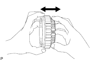
| 25. INSPECT NO. 1 SYNCHRONIZER RING SET (FOR 1ST GEAR) |
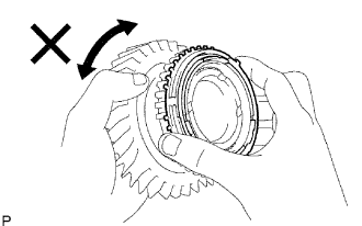 |
Apply gear oil to the cone of the 1st gear, and check that it does not turn in both directions while pushing the No. 1 synchronizer ring set.
If it turns, replace the synchronizer ring.
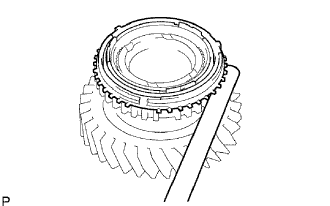 |
Measure the clearance between the No. 1 synchronizer ring and 1st gear while pushing the No. 1 synchronizer ring to the cone of the 1st gear.
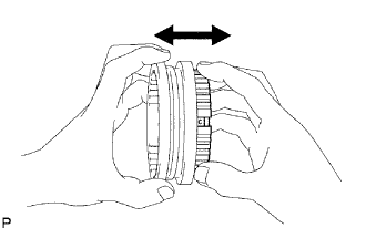
| 26. INSPECT NO. 1 SYNCHRONIZER RING SET (FOR 2ND GEAR) |
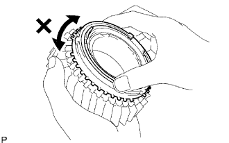 |
Apply gear oil to the cone of the 2nd gear, and check that it does not turn in both directions while pushing the No. 1 synchronizer ring set .
If it can turn, replace the No. 1 synchronizer ring set.
 |
Push the No. 1 synchronizer ring set to the cone of the 2nd gear. Measure the clearance between the No. 1 synchronizer ring set and 2nd gear.
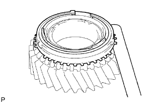
| 27. INSPECT NO. 2 SYNCHRONIZER RING (FOR 3RD GEAR) |
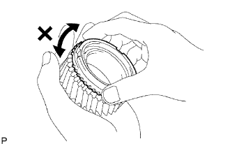 |
Apply gear oil to the cone of the 3rd gear, and check that it does not turn in both directions while pushing the No. 2 synchronizer ring (for the 3rd gear).
If it can turn, replace the No. 2 synchronizer ring.
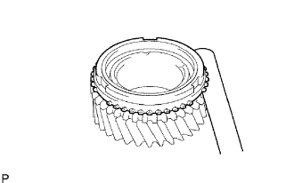 |
Push the No. 2 synchronizer ring to the cone of the 3rd gear. Measure the clearance between the No. 2 synchronizer ring (for the 3rd gear) and 3rd gear.
| 28. INSPECT REVERSE GEAR |
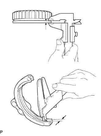 |
Using a vernier caliper, measure the reverse gear groove and the thickness of claw of the No. 1 shift fork clearance.
| 29. INSPECT NO. 1 TRANSMISSION CLUTCH HUB |
 |
Check the sliding condition between the No. 1 clutch hub and the reverse gear.
Check the tip of the spline gear sleeve of the reverse gear for wear.
If there are any defeats, replace the No. 1 clutch hub.
| 30. INSPECT NO. 2 TRANSMISSION HUB SLEEVE |
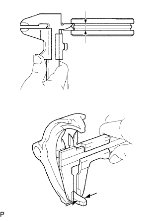 |
Using a vernier caliper, measure the No. 2 hub sleeve groove and the thickness of claw of the No. 2 shift fork.
| 31. INSPECT NO. 2 TRANSMISSION CLUTCH HUB |
 |
Check the sliding condition between the No. 2 clutch hub and No. 2 hub sleeve.
Check the tip of the spline gear of the sleeve if the No. 2 hub sleeve for wear.
