INPUT SHAFT > REMOVAL |
| 1. REMOVE NO. 2 SYNCHRONIZER RING |
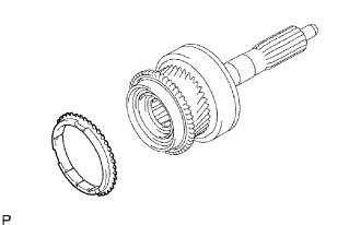 |
Remove synchronizer ring from the input shaft.
| 2. REMOVE INPUT SHAFT BEARING |
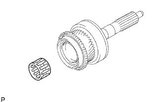 |
Remove the bearing from the input shaft.
| 3. REMOVE FRONT BEARING SHAFT SNAP RING |
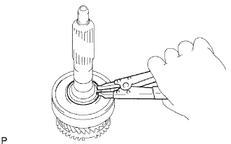 |
Using a snap ring expander, remove the snap ring from the input shaft.
| 4. REMOVE INPUT SHAFT FRONT BEARING |
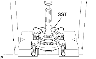 |
Using SST and a press, press out the front bearing from the input shaft.
| 5. REMOVE NO. 2 SYNCHRONIZER RING |
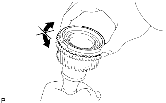 |
Apply gear oil to the cone of the input shaft, and check that it does not turn in both direction while pushing the No. 2 synchronizer ring.
If it can turn, replace the No. 1 synchronizer ring .
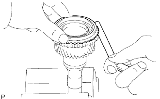 |
Push the No. 2 synchronizer ring to the cone of the input shaft. Measure the clearance between the No. 2 synchronizer ring and input shaft.
