MANUAL TRANSMISSION UNIT > REMOVAL |
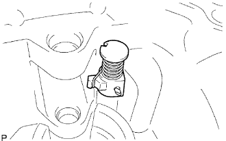
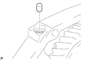
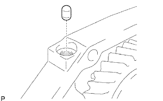
| 1. REMOVE FILLER PLUG |
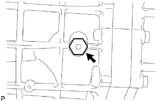 |
Remove the filler plug and gasket from the transmission case.
| 2. REMOVE DRAIN PLUG |
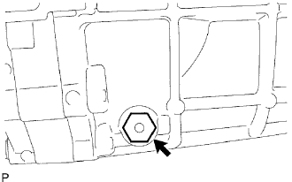 |
Remove the drain plug and gasket from the transmission case.
| 3. REMOVE CLUTCH RELEASE FORK SUB-ASSEMBLY |
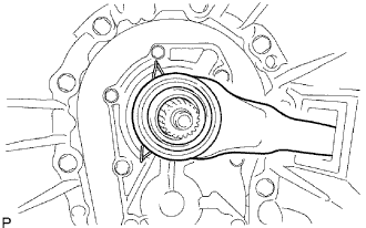 |
Remove the release fork and release bearing from the clutch housing.
| 4. REMOVE CLUTCH RELEASE BEARING ASSEMBLY |
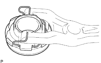 |
Remove the clip, and then remove the release bearing from the release fork.
| 5. REMOVE RELEASE FORK SUPPORT |
 |
Remove the release fork support from the clutch housing.
| 6. REMOVE CLUTCH RELEASE FORK BOOT |
 |
Remove the release fork boot from the clutch housing.
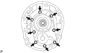
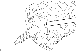
| 7. REMOVE CLUTCH HOUSING |
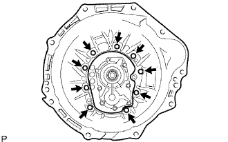 |
Remove the 9 bolts.
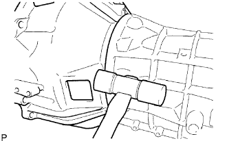 |
Using a plastic-faced hammer, tap out the clutch housing from the transmission case.
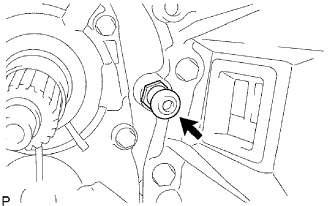
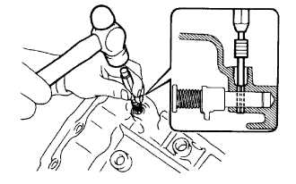
| 8. REMOVE BACK-UP LIGHT SWITCH ASSEMBLY |
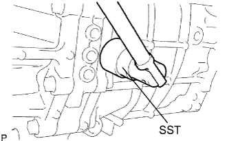 |
Using SST, remove the back-up light switch and gasket from the transmission case.
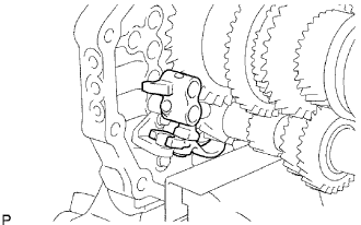
| 9. REMOVE RESTRICT PIN |
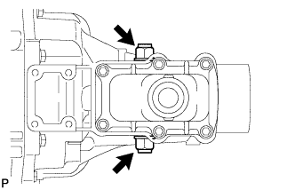 |
Remove the 2 restrict pins from the extension housing.
| 10. REMOVE CONTROL SHIFT LEVER RETAINER |
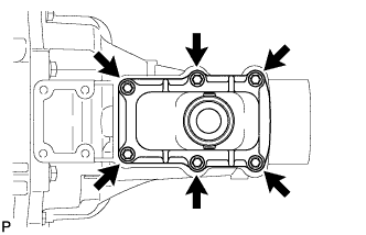 |
Remove the 6 bolts.
Remove the control shift lever retainer.
Remove the control shift lever retainer gasket.
| 11. REMOVE EXTENSION HOUSING |
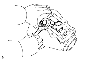 |
Remove the bolt from the shift lever housing.
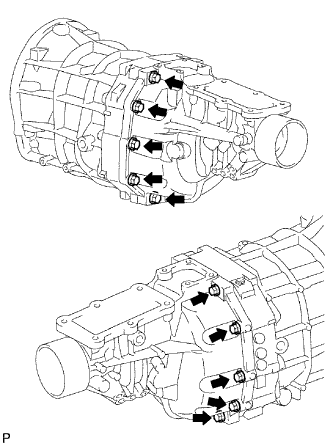 |
Remove the 10 bolts.
 |
Using a plastic-faced hammer, tap the extension housing and remove the shift lever housing and shift and select lever from the transmission case.
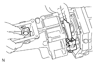
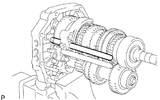
| 12. REMOVE OIL RECEIVER PIPE |
 |
| 13. REMOVE OIL RECEIVER |
Remove the bolt and oil receiver.
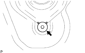
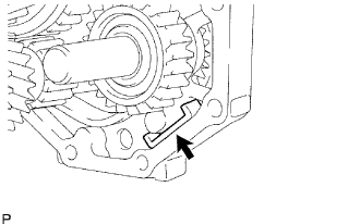
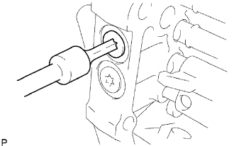
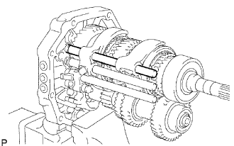
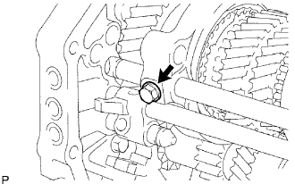
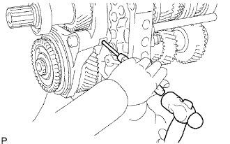
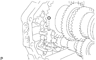
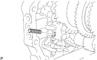
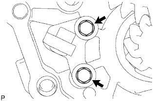
| 14. REMOVE REVERSE RESTRICT PIN |
 |
Using a T40 ''torx'' socket wrench, remove the plug.
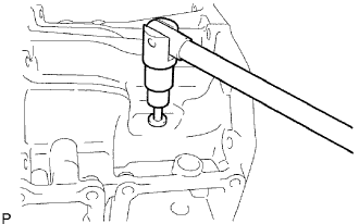
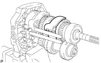
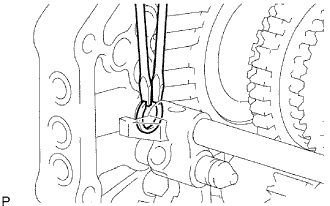
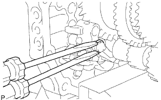
 |
Using a 5 mm pin punch and a hammer, tap out the restrict slotted pin.
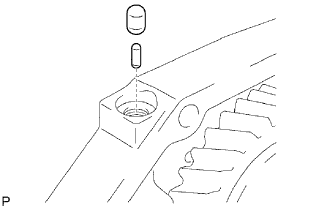
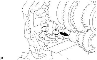
 |
Remove the restrict pin.
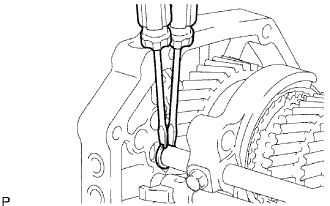
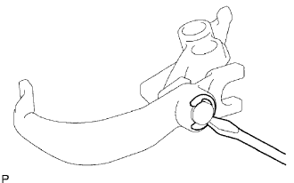
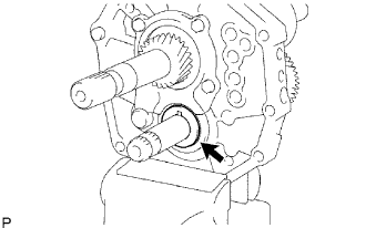
| 15. REMOVE EXTENSION HOUSING OIL SEAL |
Using a screwdriver and a hammer, tap out the oil seal from the transfer adapter.
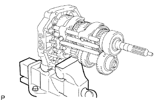
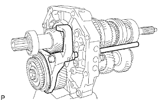
| 16. REMOVE FRONT BEARING RETAINER |
 |
Remove the 8 bolts.
 |
Using a brass bar and a hammer, tap out the retainer from the transmission case.
| 17. REMOVE TRANSMISSION FRONT BEARING RETAINER OIL SEAL |
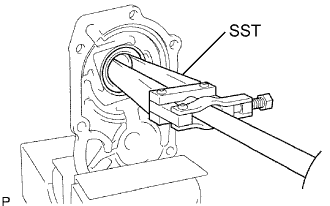 |
Fix the front bearing retainer in a vise.
Using SST, tap out the oil seal.
| 18. REMOVE FRONT BEARING SHAFT SNAP RING |
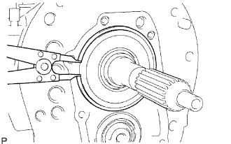 |
Using a snap ring expander, remove the snap ring from the transmission case.
| 19. REMOVE NO. 1 COUNTER GEAR FRONT BEARING SNAP RING |
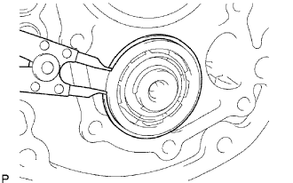 |
Using a snap ring expander, remove the snap ring from the transmission case.
| 20. REMOVE MANUAL TRANSMISSION CASE |
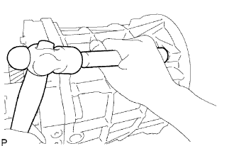 |
Using a brass bar and a hammer, tap out the transmission case from the intermediate plate.
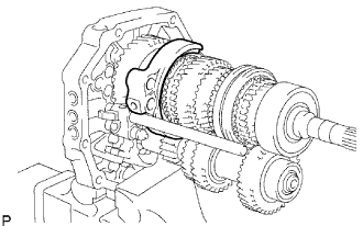
| 21. REMOVE TRANSMISSION MAGNET |
 |
Remove the magnet from the intermediate plate.
| 22. FIX INTERMEDIATE PLATE |
 |
Fix the intermediate plate in a vise between the aluminum plates.
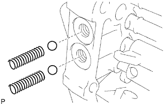
| 23. REMOVE NO. 1 SHIFT DETENT BALL SPRING SEAT |
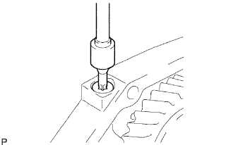 |
Using a T40 ''torx'' socket wrench, remove the spring seat from the intermediate plate.
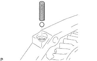 |
Using a magnetic finger, remove the compression spring and detent ball from the intermediate plate.
 |
Using a T40 ''torx'' socket wrench, remove the 2 spring seats from the intermediate plate.
 |
Using a magnetic finger, remove the 2 compression springs and 2 detent balls from the intermediate plate.
| 24. REMOVE NO. 2 SHIFT FORK SHAFT |
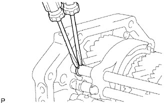 |
Using 2 screwdrivers and a hammer, tap out the snap ring from the No. 2 shift fork shaft.
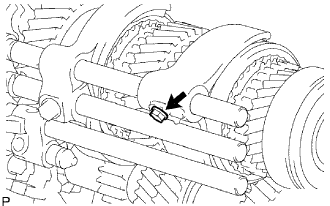 |
Remove the bolt from the No. 2 shift fork.
 |
Remove the No. 2 shift fork shaft from the intermediate plate.
 |
Remove the No. 2 shift fork from the No. 2 transmission hub sleeve.
 |
Using a magnetic finger, remove the No. 1 shift interlock roller and shift interlock pin from the intermediate plate.
| 25. REMOVE NO. 1 SHIFT FORK SHAFT |
 |
Using 2 screwdrivers and a hammer, tap out the snap ring from the No. 1 shift fork shaft.
 |
Remove the shift fork set bolt from the No. 1 shift fork.
 |
Remove the No. 1 shift fork shaft from the intermediate plate.
 |
Remove the No. 1 shift fork from the reverse gear.
 |
Using a magnetic finger, remove the No. 1 shift interlock roller from the intermediate plate.
| 26. REMOVE NO. 3 SHIFT FORK SHAFT |
 |
Using a 5 mm pin punch and a hammer, tap out the shift fork set slotted pin from the No. 3 shift fork.
 |
Using 2 screwdrivers and a hammer, tap out the snap ring from the shift fork shaft.
 |
Remove the No. 3 shift fork and No. 3 shift fork shaft from the intermediate plate.
 |
Using a magnetic finger, remove the No. 1 shift interlock roller from the intermediate plate.
 |
Using a magnetic finger, remove the reverse shift fork ball from the reverse shift fork.
| 27. REMOVE NO. 4 SHIFT FORK SHAFT |
 |
Using 2 screwdrivers and a hammer, tap out the snap ring from the No. 4 shift fork shaft.
 |
Remove the No. 4 shift fork shaft from the intermediate plate.
 |
Using a magnetic finger, remove the reverse shift fork return compression spring from the reverse shift fork.
| 28. REMOVE REVERSE SHIFT FORK |
 |
Remove the reverse shift fork (with the reverse shift arm) from the intermediate plate.
 |
Using a screwdriver, pry out the E-ring and reverse shift fork from the reverse shift arm.
| 29. REMOVE REVERSE SHIFT ARM BRACKET |
 |
Remove the 2 bolts and reverse shift arm bracket from the intermediate plate.
| 30. REMOVE SPEEDOMETER DRIVE GEAR |
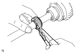 |
Using snap ring pliers, remove the snap ring.
Remove the drive gear.
Using a magnetic finger, remove the steel ball.
Using snap ring pliers, remove the snap ring.
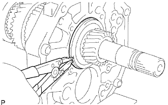
| 31. REMOVE OUTPUT SHAFT BEARING SHAFT SNAP RING |
 |
Using 2 screwdrivers and a hammer, tap out the shaft snap ring from the output shaft.
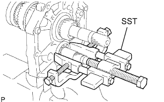
| 32. REMOVE OUTPUT SHAFT REAR BEARING |
 |
Using SST, remove the rear bearing and output shaft spacer from the output shaft.
| 33. INSPECT COUNTER 5TH GEAR CLEARANCE |
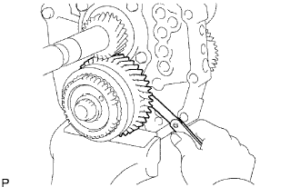 |
Using a feeler gauge, measure the thrust clearance.
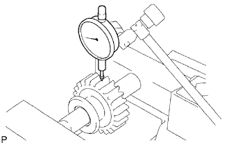
| 34. INSPECT COUNTER 5TH GEAR RADIAL CLEARANCE |
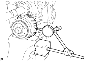 |
Using a dial indicator, measure the radial clearance.
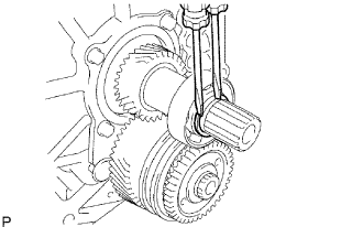
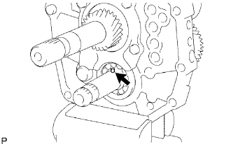
| 35. REMOVE COUNTER GEAR REAR SHAFT SNAP RING |
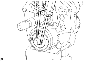 |
Using 2 screwdrivers and a hammer, tap out the snap ring from the counter gear.
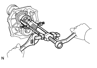
| 36. REMOVE NO. 5 GEAR SPRING PIECE |
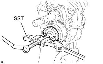 |
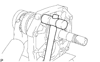
Using SST, remove the gear spline piece from the counter gear.
| 37. REMOVE NO. 3 SYNCHRONIZER RING |
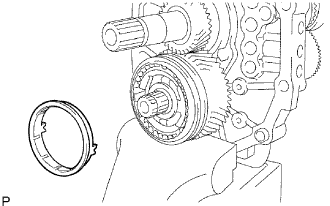 |
Remove the synchronizer ring from the counter gear.
| 38. REMOVE COUNTER 5TH GEAR |
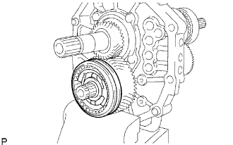 |
Remove the counter 5th gear and No. 3 transmission hub sleeve assembly from the counter gear.
| 39. REMOVE COUNTER 5TH GEAR BEARING |
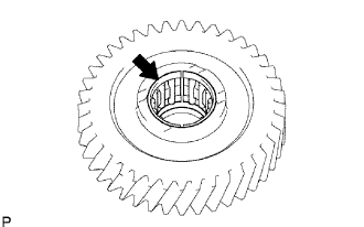 |
Remove the bearing from the counter 5th gear.
| 40. REMOVE NO. 3 TRANSMISSION HUB SLEEVE |
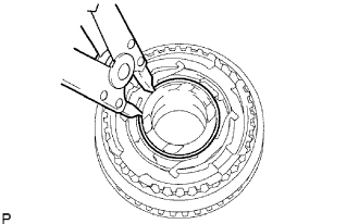 |
Using a snap ring expander, remove the snap ring.
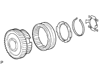 |
Remove the No. 3 transmission hub sleeve, 2 No. 3 synchromesh shifting keys and 2 No. 3 synchromesh shifting key springs from the counter 5th gear.
| 41. REMOVE 5TH GEAR THRUST WASHER |
 |
Remove the thrust washer from the counter gear.
| 42. REMOVE 5TH GEAR THRUST WASHER PIN |
 |
Remove the thrust washer pin from the counter gear.
| 43. REMOVE REAR BEARING RETAINER |
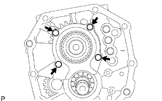 |
Remove the 4 bolts and bearing retainer from the intermediate plate.
| 44. REMOVE REVERSE IDLER GEAR |
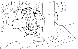 |
Pull out the reverse idler gear shaft to the rear side and remove the reverse idler gear from the intermediate plate.
| 45. REMOVE COUNTER SHAFT CENTER BEARING |
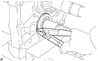 |
Using a snap ring expander, remove the snap ring.
 |
Using SST, remove the center bearing from the intermediate plate.
| 46. REMOVE COUNTER GEAR |
 |
Remove the counter gear from the intermediate plate.
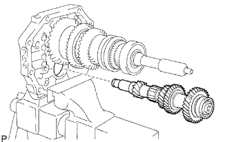
| 47. REMOVE INPUT SHAFT ASSEMBLY |
 |
Remove the input shaft and No. 2 synchronizer ring from the output shaft.
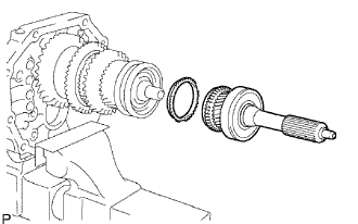
| 48. REMOVE OUTPUT SHAFT BEARING SHAFT SNAP RING |
 |
Using a snap ring expander, remove the snap ring from the output shaft.
| 49. REMOVE OUTPUT SHAFT ASSEMBLY |
 |
Using a plastic-faced hammer, remove the output shaft by tapping the intermediate plate.
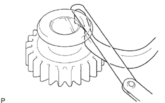
| 50. INSPECT NO. 3 SYNCHRONIZER RING |
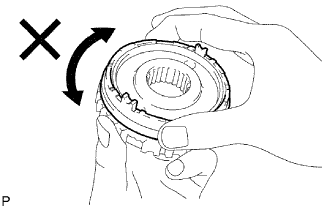 |
Apply gear oil to the cone part of the No. 5 gear spline piece, and check that it does not turn in both directions while pushing the No. 3 synchronizer ring to the No. 5 gear spline piece.
If it can turn, replace the No. 3 synchronizer ring.
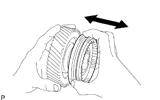
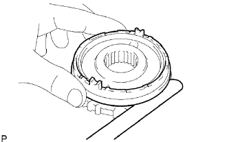 |
Push the No. 3 synchronizer ring outer to the cone part of the No. 5 gear spline piece. Measure the clearance between the No. 3 synchronizer ring outer and No. 5 gear spline piece.
| 51. INSPECT NO. 3 TRANSMISSION HUB SLEEVE |
 |
Check the sliding condition between the counter shaft 5th gear and No. 3 transmission hub sleeve.
Check the tip of the spline gear of the No. 3 transmission hub sleeve for wear.
If there are any defects, replace the No. 3 transmission hub sleeve.
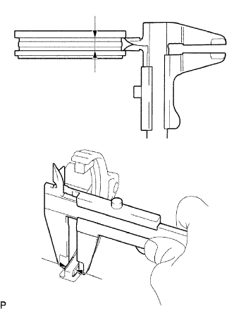 |
Using a vernier caliper, measure the No. 3 transmission hub sleeve groove and the thickness of the claw part of the No. 3 shift fork to calculate the clearance.
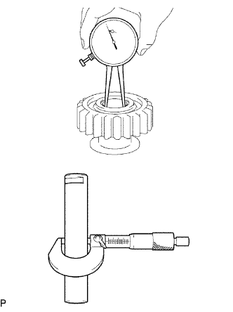
| 52. INSPECT COUNTER 5TH GEAR |
 |
Using a cylinder gauge, measure the inside diameter of the counter 5th gear.
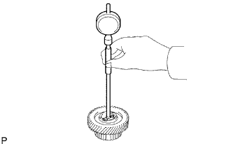
| 53. INSPECT REVERSE IDLER GEAR SUB-ASSEMBLY |
 |
Using a caliper gauge, measure the inside diameter of the reverse idler gear.
Using a micrometer, measure the diameter of the sliding part of the reverse idler gear on the reverse idler gear shaft.
 |
Using a feeler gauge, measure the thrust clearance of the shoe part between the reverse idler gear and reverse shift arm.
| 54. INSPECT REVERSE IDLER GEAR RADIAL CLEARANCE |
 |
Install the reverse idler gear on the reverse idler gear shaft, and clamp it to a vise.
Using a dial indicator, measure the radical clearance.
