MANUAL TRANSMISSION UNIT > INSTALLATION |
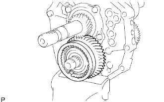
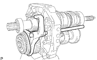
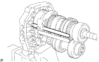
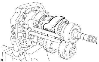
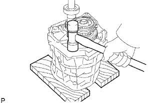
| 1. INSTALL OUTPUT SHAFT ASSEMBLY |
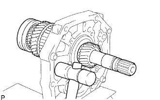 |
Apply gear oil to the sliding part of the output shaft.
Using a plastic-faced hammer, install the output shaft by rapping the intermediate plate.
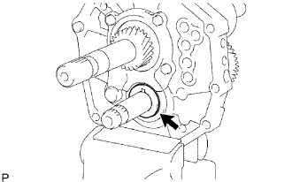
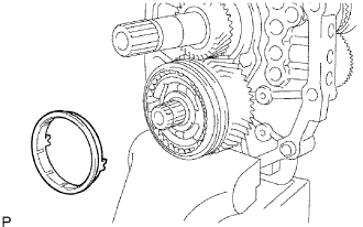
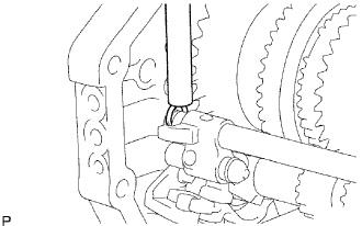
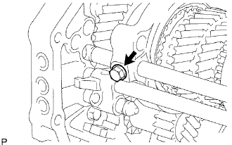
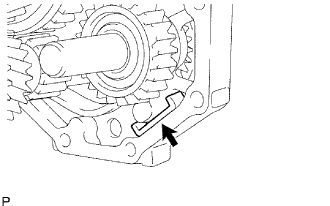
| 2. INSTALL OUTPUT SHAFT BEARING SHAFT SNAP RING |
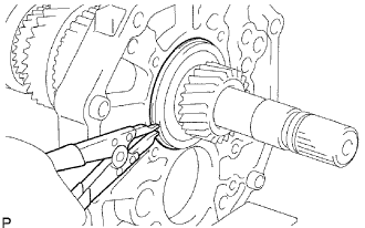 |
Using a snap ring expander, install the shaft snap ring to the output shaft.
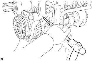
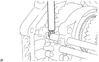
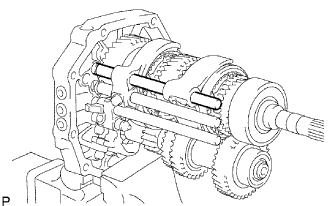
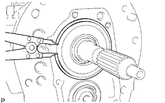
| 3. INSTALL INPUT SHAFT ASSEMBLY |
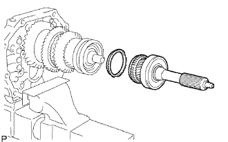 |
Apply gear oil to the input shaft and No. 2 synchronizer ring, and install them to the output shaft.
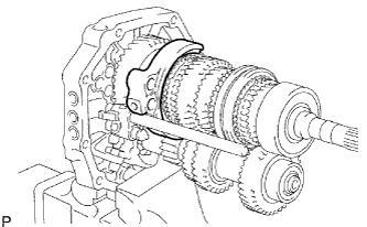
| 4. INSTALL COUNTER GEAR |
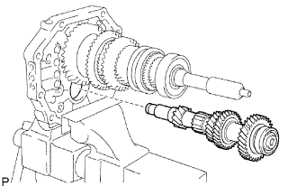 |
Temporarily install the counter gear to the intermediate plate.
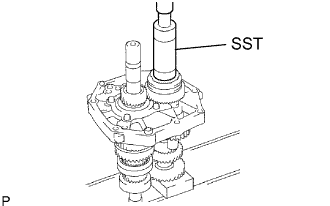
| 5. INSTALL COUNTER SHAFT CENTER BEARING |
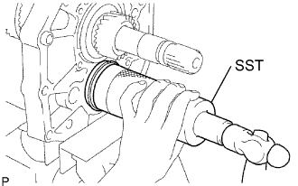 |
Using SST and a hammer, tap in a new center bearing to the intermediate plate.
| 6. INSTALL REVERSE IDLER GEAR |
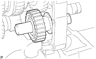 |
Apply gear oil to each sliding part of the reverse idler gear and the reverse idler gear shaft, and install the reverse idler gear and the reverse idler shaft to the intermediate plate.
| 7. INSTALL REAR BEARING RETAINER |
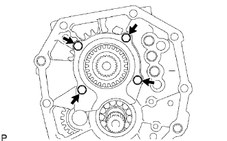 |
Install the bearing retainer inserting to the groove of the reverse idler gear shaft with the 4 bolts.
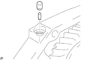
| 8. INSTALL 5TH GEAR THRUST WASHER PIN |
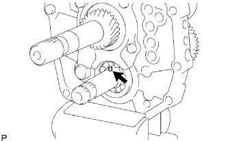 |
Apply MP grease to the washer pin, and install it to the counter gear.
| 9. INSTALL 5TH GEAR THRUST WASHER |
 |
Apply gear oil to the thrust washer, and install it to the counter gear.
| 10. INSTALL NO. 3 TRANSMISSION HUB SLEEVE |
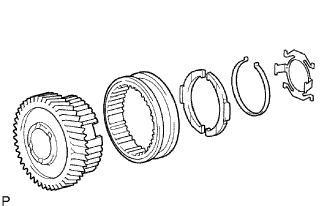 |
Apply gear oil to the sliding part of No. 3 transmission hub sleeve, and install it to the counter 5th gear.
Install the 2 No. 3 synchromesh shifting keys and 2 synchromesh shifting key springs to the counter 5th gear.
 |
Using a snap ring expander, install the snap ring to the counter 5th gear.
| 11. INSTALL COUNTER 5TH GEAR BEARING |
 |
Apply gear oil to the bearing and install it to the counter 5th gear.
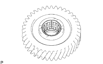
| 12. INSTALL COUNTER 5TH GEAR |
 |
Apply gear oil to the 5th gear and No. 3 transmission hub sleeve, and install it to the counter gear.
| 13. INSTALL NO. 3 SYNCHRONIZER RING |
 |
Apply gear oil to the No. 3 synchronizer ring, and install it to the counter gear.
| 14. INSTALL NO. 5 GEAR SPLINE PIECE |
 |
Using SST and a press, press in the gear spline piece to the counter gear.
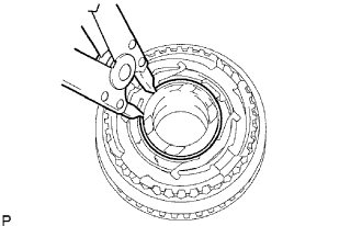
| 15. INSTALL COUNTER GEAR REAR SHAFT SNAP RING |
Select the snap ring so that the thrust gap between the No. 5 gear spline piece and snap ring to be within the specification.
| Mark | Thickness |
| A | 2.80 to 2.85 mm (0.1102 to 0.1122 in.) |
| B | 2.85 to 2.90 mm (0.1122 to 0.1141 in.) |
| C | 2.90 to 2.95 mm (0.1141 to 0.1160 in.) |
| D | 2.95 to 3.00 mm (0.1160 to 0.1181 in.) |
| E | 3.00 to 3.05 mm (0.1181 to 0.1200 in.) |
| F | 3.05 to 3.10 mm (0.1200 to 0.1220 in.) |
| G | 3.10 to 3.15 mm (0.1220 to 0.1240 in.) |
 |
Using a brass bar and hammer, tap in the snap ring.
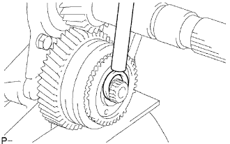
| 16. INSPECT COUNTER 5TH GEAR THRUST CLEARANCE |
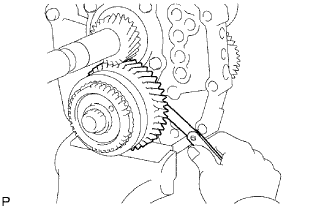 |
Using a feeler gauge, measure the thrust clearance.
| 17. INSPECT COUNTER 5TH GEAR RADIAL CLEARANCE |
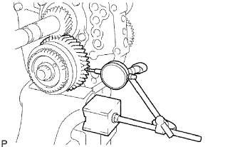 |
Using a dial indicator, check the gear radial clearance.
| 18. INSTALL OUTPUT SHAFT REAR BEARING |
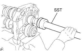 |
Using SST and a press, press in the spacer and a new rear bearing to the output shaft.
| 19. INSTALL OUTPUT SHAFT BEARING SHAFT SNAP RING |
Select a shaft snap ring so that the thrust gap between the output shaft bearing shaft and snap ring to be within the specification.
| Mark | Thickness | Mark | Thickness |
| A | 2.65 to 2.70 mm (0.1043 to 0.1063 in.) | K | 3.10 to 3.15 mm (0.1220 to 0.1240 in.) |
| B | 2.70 to 2.75 mm (0.1063 to 0.1083 in.) | L | 3.15 to 3.20 mm (0.1240 to 0.1260 in.) |
| C | 2.75 to 2.80 mm (0.1083 to 0.1102 in.) | M | 3.20 to 3.25 mm (0.1260 to 0.1280 in.) |
| D | 2.80 to 2.85 mm (0.1102 to 0.1122 in.) | N | 3.25 to 3.30 mm (0.1280 to 0.1299 in.) |
| E | 2.85 to 2.90 mm (0.1122 to 0.1141 in.) | P | 3.30 to 3.35 mm (0.1299 to 0.1319 in.) |
| F | 2.90 to 2.95 mm (0.1141 to 0.1160 in.) | Q | 3.35 to 3.40 mm (0.1319 to 0.1339 in.) |
| G | 2.95 to 3.00 mm (0.1160 to 0.1181 in.) | R | 3.40 to 3.45 mm (0.1339 to 0.1358 in.) |
| H | 3.00 to 3.05 mm (0.1181 to 0.1200 in.) | S | 3.45 to 3.50 mm (0.1358 to 0.1378 in.) |
| J | 3.05 to 3.10 mm (0.1200 to 0.1220 in.) |
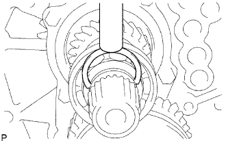 |
Using a brass bar and hammer, tap in the snap ring.
| 20. INSTALL REVERSE SHIFT ARM BRACKET |
 |
Install the arm bracket on the intermediate plate with the 2 bolts.
| 21. INSTALL REVERSE SHIFT FORK |
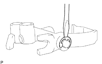 |
Install the shift arm to the shift fork. Using a screwdriver and hammer, tap in a new E-ring.
 |
Install the tip of the reverse shift arm to the reverse idler gear. Align the cut end of the reverse shift arm with the reverse shift arm bracket pin, and install them.
| 22. INSTALL NO. 4 SHIFT FORK SHAFT |
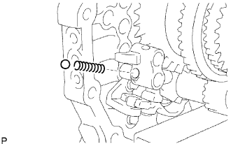 |
Install the compression spring and reverse shift fork ball to the reverse shift fork.
 |
Apply gear oil to the sliding part of the No. 4 shift fork shaft.
Using a screwdriver, install the No. 3 shift fork shaft by pushing the reverse shift fork ball lightly.
 |
Using a brass bar and a hammer, tap in the snap ring to the No. 4 shift fork shaft.
| 23. INSTALL NO. 3 SHIFT FORK SHAFT |
 |
Install the reverse shift fork ball to the reverse shift fork.
 |
Install the No. 1 shift interlock roller to the intermediate plate.
 |
Install the No. 3 shift fork to the No. 3 transmission hub sleeve and No. 3 shift fork shaft to the intermediate plate from the front side.
 |
Using a brass bar and hammer, tap in the snap ring to the shift fork shaft.
 |
Using a 5 mm pin punch and hammer, tap in the slotted spring pin to the No. 3 shift fork.
| 24. INSTALL NO. 1 SHIFT FORK SHAFT |
 |
Install the No. 1 shift interlock roller to the intermediate plate.
 |
Install the No. 1 shift fork to the reverse gear.
 |
Install the No. 1 shift fork shaft to the intermediate plate from the rear side.
 |
Install the shift fork set bolt to the No. 1 shift fork.
 |
Using a brass bar and hammer, tap in the shift fork shaft snap ring to the No. 1 shift fork shaft.
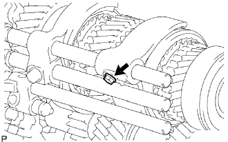
| 25. INSTALL NO. 2 SHIFT SHAFT |
 |
Install the shift interlock pin and No. 1 shift interlock roller to the intermediate plate.
 |
Install the No. 2 shift fork to the No. 2 transmission hub sleeve.
 |
Apply gear oil to the No. 2 shift fork, and install to the intermediate plate from the rear side.
 |
Install the shift fork set bolt to the No. 2 shift fork.
 |
Using a brass bar and a hammer, tap in the snap ring to the No. 2 shift fork shaft.
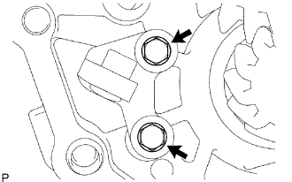
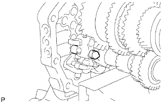
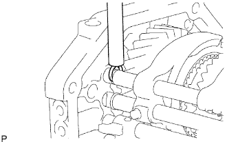
| 26. INSTALL NO. 1 SHIFT DETENT BALL SPRING SEAT |
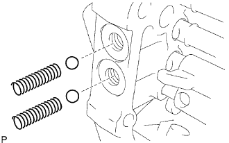 |
Install the 2 compression springs and 2 shifts detent balls to the intermediate plate.
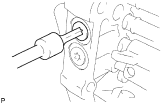 |
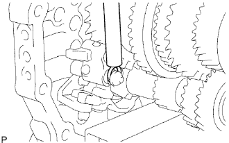
Using a T40 ''torx'' socket wrench, install the 3 spring seats to the intermediate plate.
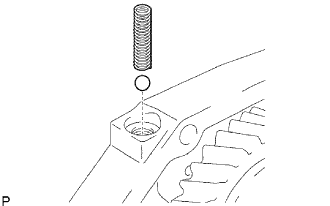 |
Install the detent ball and low side compression spring to the intermediate plate.
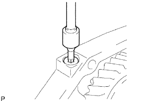 |
Using a T40 ''torx'' socket wrench, install the spring seat to the intermediate plate.
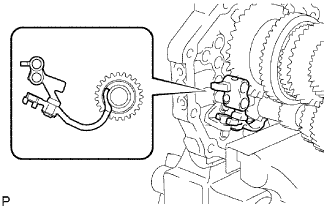
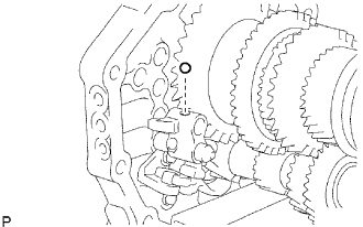
| 27. INSTALL TRANSMISSION MAGNET |
 |
Clean the transmission magnet, and install it to the intermediate plate.
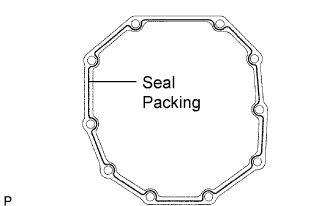
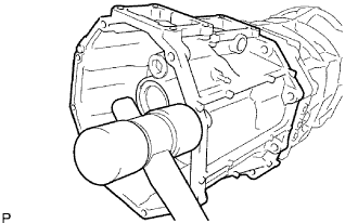
| 28. INSTALL MANUAL TRANSMISSION CASE |
 |
Apply seal packing to the manual transmission case as shown in the illustration.
 |
Using a plastic-faced hammer, tap the transmission case to attach it to the intermediate plate.
| 29. INSTALL NO. 1 COUNTER GEAR FRONT BEARING SNAP RING |
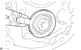 |
Using a snap rig expander, install the snap ring to the transmission case.
| 30. INSTALL FRONT BEARING SHAFT SNAP RING |
 |
Using a snap rig expander, install the snap ring to the transmission case.
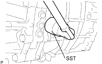
| 31. INSTALL TRANSMISSION FRONT BEARING RETAINER OIL SEAL |
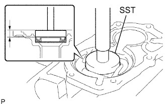 |
Using SST and a hammer, tap in a new oil seal to the front bearing retainer.
Lightly apply MP grease to the tip of the oil seal.
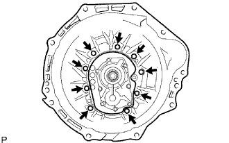
| 32. INSTALL FRONT BEARING RETAINER |
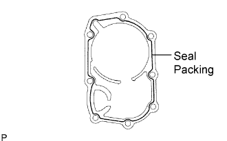 |
Apply seal packing to the bearing retainer as shown in the illustration.
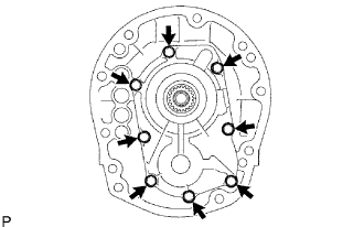 |
Install the front bearing retainer to the transmission case with the 8 bolts.
Check that the input shaft and output shaft rotate smoothly.
| 33. INSTALL TRANSFER ADAPTER OIL SEAL |
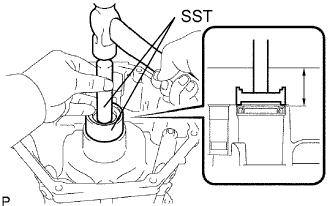 |
Using SST and a hammer, tap in a new oil seal to the transfer adapter.
Lightly apply MP grease to the tip of the oil seal.
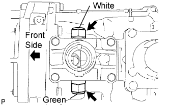
| 34. INSTALL REVERSE RESTRICT PIN |
 |
Install the restrict pin to the transfer adapter.
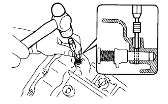 |
Using a 5 mm pin punch and hammer, tap in the slotted pin to the transfer adapter.
 |
Using a T40 ''torx'' socket wrench, install the reverse restrict pin plug to the transfer adapter.
| 35. INSTALL OIL RECEIVER PIPE |
 |
Install the oil receiver pipe to the transfer adapter.
| 36. INSTALL TRANSFER ADAPTER |
 |
Apply seal packing to the transfer adapter as shown in the illustration.
 |
Using a plastic-faced hammer, tap the transfer adapter to attach it to the transmission case.
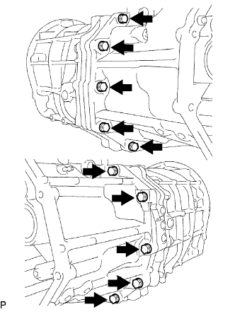 |
Install the transfer adapter to the transmission case with the 10 bolts.
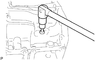
| 37. INSTALL SHIFT AND SELECT LEVER SHAFT |
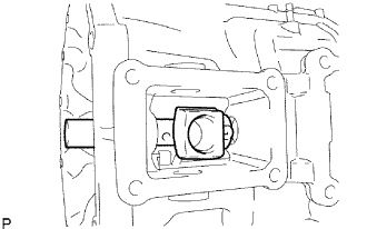 |
Install the shift and select lever shaft and shift lever housing to the transfer adapter.
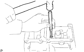 |
Using a 5 mm pin punch and hammer, tap in the slotted spring pin to the transfer adapter.
| 38. INSTALL TRANSFER CONTROL SHIFT LEVER RETAINER |
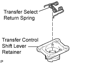 |
Install the select return spring on the shift lever retainer.
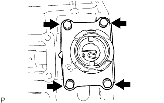 |
Install the shift lever retainer to the transfer adapter with the 4 bolts.
| 39. INSTALL CONTROL SHIFT LEVER RETAINER |
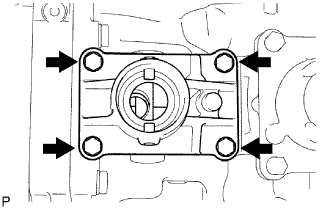 |
Install the control shift lever retainer and oil deflector.
Install the 4 bolts.
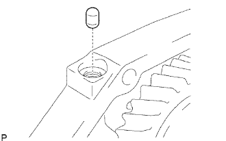
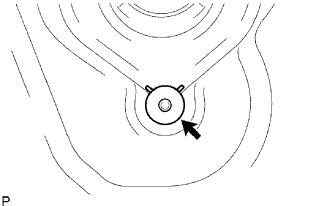
| 40. INSTALL RESTRICT PIN |
 |
Install the 2 restrict pins.
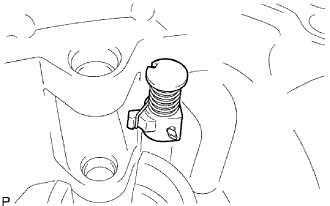
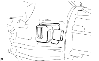
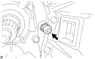
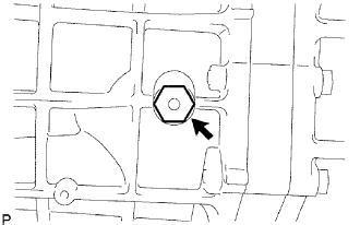
| 41. INSTALL BACK-UP LIGHT SWITCH ASSEMBLY |
 |
Using SST, install a new gasket and back-up light switch and to the transmission case.
| 42. INSTALL CLUTCH HOUSING |
 |
Install the clutch housing to the transmission case with the 9 bolts.
| 43. INSTALL CLUTCH RELEASE FORK BOOT |
 |
Install the fork boot to the clutch housing.
| 44. INSTALL RELEASE FORK SUPPORT |
 |
Install the release fork support to the clutch housing.
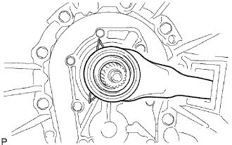
| 45. INSTALL CLUTCH RELEASE BEARING ASSEMBLY |
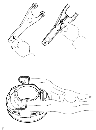 |
Apply clutch release hub grease to the clutch release bearing, and install it to the clutch release fork.
| 46. INSTALL CLUTCH RELEASE FORK SUB-ASSEMBLY |
 |
Install the clutch release fork.
Apply the clutch spline grease to the spline of the input shaft.
| 47. INSTALL DRAIN PLUG |
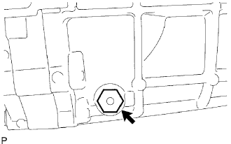 |
Install a new gasket and drain plug to the transmission case.
| 48. INSTALL FILLER PLUG |
 |
Install a new gasket and filler plug to the transmission case.
