TRANSFER SYSTEM > ON-VEHICLE INSPECTION

for Preparation Click here


1. TRANSFER SYSTEM

NOTICE:
  1. To shift from H2 to H4, reduce the vehicle's speed to less than 80 km/h (50 mph) and move the transfer shift lever.
  2. A/T: To shift from H4 to L4, stop the vehicle, move hte shift lever to N and then move the transfer shift lever.
  3. A/T: To shift from L4 to H4, stop the vehicle, move the shift lever to N and then move the transfer shift lever.
  4. M/T: To shift from H4 to L4, stop the vehicle or reduce the vehicle's speed to less than 5 km/h (3 mph). Release the accelerator pedal, depress the clutch pedal and move the transfer shift lever.
  5. M/T: To shift from L4 to H4, depress the clutch pedal and move the transfer shift lever.


2. CHECK H2 (2WD) - H4 OR L4 (4WD) SHIFT


G100315E02
  1. Start the engine.

  1. Move the transfer shift lever from the H2 position to the H4 or L4 position.

  1. Check that the 4WD indicator light illuminates.

  1. Move the transfer shift lever from the H4 or L4 position to the H2 position.

  1. Check that the 4WD indicator light turns off.

    HINT:
    1. If the indicator lamp does not turn off when you move the transfer shift lever into H2, drive straight ahead while accelerating or decelerating, or drive in reverse.
    2. If a shift is uncompleted for 30 minutes, the 4WD indicator light will begin flashing.


3. CHECK 4WD CONTROL ECU


G100317E01

  1. Measure the voltage and resistance of the connector.

    Standard voltage:

    Tester Connection
    Wiring Color
    Condition
    Specified Condition
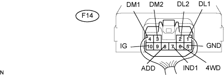
    F14-10 (IG) - F14-5 (GND)
    B-Y - W-B
    Ignition switch ON
    10 to 14 V
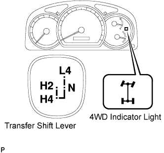
    F14-7 (IND1) - F14-5 (GND)
    W-R - W-B
    Ignition switch ON and transfer shift lever position H2
    10 to 14 V
    F14-7 (IND1) -F14-5 (GND)
    W-R - W-B
    Ignition switch ON and transfer shift lever position H4 or L4
    0 to 3.5 V
    F14-8 (ADD) - F14-5 (GND)
    R-B - W-B
    Ignition switch ON and A.D.D. NOT LOCKED
    10 to 14 V
    F14-8 (ADD) - F14-5 (GND)
    R-B - W-B
    Ignition switch ON and A.D.D. LOCKED
    Below 1.5 V
    F14-6 (4WD) - F14-5 (GND)
    B - W-B
    Ignition switch ON and transfer shift lever position H2
    10 to 14 V
    F14-6 (DL) - F14-5 (GND)
    B - W-B
    Ignition switch ON and transfer shift lever position H4 or L4
    Below 1.5 V
    F14-1 (DL1) - F14-5 (GND)
    R-Y - W-B
    Ignition switch ON and A.D.D. NOT LOCKED
    Below 1.5 V
    F14-1 (DL1) - F14-5 (GND)
    R-Y - W-B
    Ignition switch ON and A.D.D. LOCKED
    10 to 14 V
    F14-2 (DL2) - F14-5 (GND)
    R-W - W-B
    Ignition switch ON and A.D.D. LOCKED
    Below 1.5 V
    F14-2 (DL2) - F14-5 (GND)
    R-W - W-B
    Ignition switch ON and A.D.D. NOT LOCKED
    10 to 14 V
    F14-4 (DM1) - F14-3 (DM2)
    Y - R
    Ignition switch ON and A.D.D. NOT LOCKED → LOCKED
    10 to 14 V or 0 to 14 V pulse generation → less than 0.5 V
    F14-3 (DM2) - F14-4 (DM1)
    R - Y
    Ignition switch ON and A.D.D. LOCKED → NOT LOCKED
    10 to 14 V or 0 to 14 V pulse generation → less than 0.5 V


    Standard resistance:

    Tester Connection
    Wiring Color
    Condition
    Specified Condition
    F14-5 (GND) - Body ground
    W-B - Body ground
    Always
    Below 1 Ω

    1. If the result is not as specified, the 4WD control ECU may have a malfunction.