POWER WINDOW CONTROL SYSTEM > Rear Power Window LH does not Operate with Rear Power Window Switch LH |
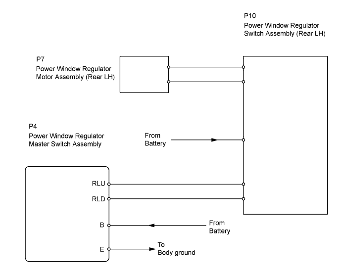
| 1.CHECK POWER WINDOW REGULATOR SWITCH ASSEMBLY (REAR LH) (POWER SOURCE) |
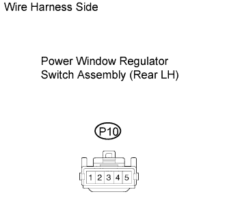 |
Disconnect the P10 regulator switch connector.
Measure the voltage of the wire harness side connector.
| Tester Connection | Condition | Specified Condition |
| P10-3 - Body ground | Ignition switch ON | 10 to 14 V |
|
| ||||
| OK | |
| 2.INSPECT POWER WINDOW REGULATOR SWITCH ASSEMBLY (REAR LH) |
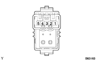 |
Remove the switch.
Measure the resistance of the switch when the switch is operated.
| Tester Connection | Switch Condition | Specified Condition |
| 5 - 4 2 - 3 | UP | Below 1 Ω |
| 5 - 4 2 - 1 | OFF | Below 1 Ω |
| 5 - 3 2 - 1 | DOWN | Below 1 Ω |
|
| ||||
| OK | |
| 3.CHECK WIRE HARNESS (SWITCH (REAR LH) - MOTOR (REAR LH)) |
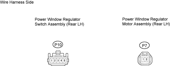
Disconnect the P10 switch connector.
Disconnect the P7 motor connector.
Measure the resistance of the wire harness side connectors.
| Tester Connection | Specified Condition |
| P10-5 - P7-1 | Below 1 Ω |
| P10-2 - P7-2 | Below 1 Ω |
| P10-5 or P7-1 - Body ground | 10 kΩ or higher |
| P10-2 or P7-2 - Body ground | 10 kΩ or higher |
|
| ||||
| OK | |
| 4.INSPECT POWER WINDOW REGULATOR MOTOR ASSEMBLY (REAR LH) |
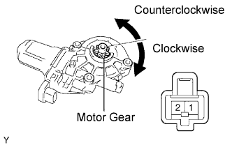 |
Remove the motor.
Apply battery voltage to connector terminals 1 and 2.
Check that the motor gear rotates smoothly as follows.
| Measurement Condition | Specified Condition |
| Battery positive (+) → 1 Battery negative (-) → 2 | Motor gear rotates clockwise |
| Battery positive (+) → 2 Battery negative (-) → 1 | Motor gear rotates counterclockwise |
|
| ||||
| OK | |
| 5.CHECK WIRE HARNESS (MASTER SWITCH - SWITCH (REAR LH)) |
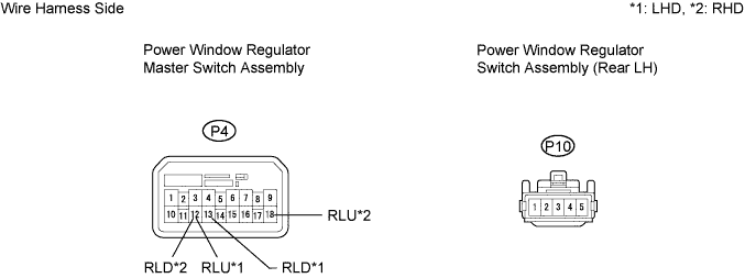
Disconnect the P4 master switch connector.
Disconnect the P10 switch connector.
Measure the resistance of the wire harness side connectors.
| Tester Connection | Specified Condition |
| P4-12 (RLU) - P10-1 | Below 1 Ω |
| P4-13 (RLD) - P10-4 | Below 1 Ω |
| P4-12 (RLU) or P10-1 - Body ground | 10 kΩ or higher |
| P4-13 (RLD) or P10-4 - Body ground | 10 kΩ or higher |
| Tester Connection | Specified Condition |
| P4-18 (RLU) - P10-1 | Below 1 Ω |
| P4-12 (RLD) - P10-4 | Below 1 Ω |
| P4-18 (RLU) or P10-1 - Body ground | 10 kΩ or higher |
| P4-12 (RLD) or P10-4 - Body ground | 10 kΩ or higher |
|
| ||||
| OK | |
| 6.INSPECT POWER WINDOW REGULATOR MASTER SWITCH ASSEMBLY (REAR LH SWITCH) |
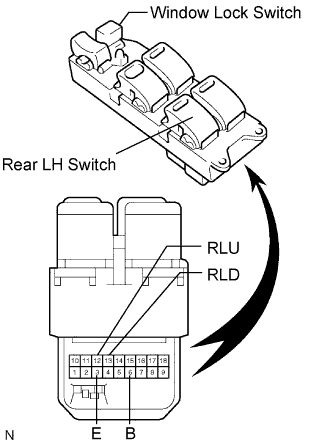 |
LHD:
Inspect the rear LH switch.
Remove the master switch.
Measure the resistance of the switch when the switch is operated.
| Window Lock Switch Condition | Power Window Switch Condition | Tester Connection | Specified Condition |
| OFF | UP | 3 (E) - 13 (RLD) 6 (B) - 12 (RLU) | Below 1 Ω |
| OFF | OFF | 3 (E) - 12 (RLU) 3 (E) - 13 (RLD) | Below 1 Ω |
| OFF | DOWN | 3 (E) - 12 (RLU) 6 (B) - 13 (RLD) | Below 1 Ω |
| ON | UP | 3 (E) - 13 (RLD) | 10 kΩ or higher |
| 6 (B) - 12 (RLU) | Below 1 Ω | ||
| ON | OFF | 12 (RLU) - 13 (RLD) | Below 1 Ω |
| ON | DOWN | 3 (E) - 12 (RLU) | 10 kΩ or higher |
| 6 (B) - 13 (RLD) | Below 1 Ω |
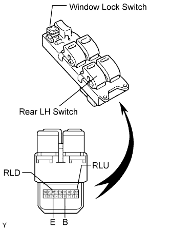 |
RHD:
Inspect the rear LH switch.
Remove the master switch.
Measure the resistance of the switch when the switch is operated.
| Window Lock Switch Condition | Power Window Switch Condition | Tester Connection | Specified Condition |
| OFF | UP | 3 (E) - 12 (RLD) 6 (B) - 18 (RLU) | Below 1 Ω |
| OFF | OFF | 3 (E) - 18 (RLU) 3 (E) - 12 (RLD) | Below 1 Ω |
| OFF | DOWN | 3 (E) - 18 (RLU) 6 (B) - 12 (RLD) | Below 1 Ω |
| ON | UP | 3 (E) - 12 (RLD) | 10 kΩ or higher |
| 6 (B) - 18 (RLU) | Below 1 Ω | ||
| ON | OFF | 12 (RLD) - 18 (RLU) | Below 1 Ω |
| ON | DOWN | 3 (E) - 18 (RLU) | 10 kΩ or higher |
| 6 (B) - 12 (RLD) | Below 1 Ω |
|
| ||||
| OK | ||
| ||
