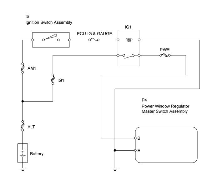
POWER WINDOW CONTROL SYSTEM > Power Windows do not Operate at All |
| 1.INSPECT FUSE (ECU-IG & GAUGE) |
Remove the ECU-IG & GAUGE fuse from the instrument panel junction block.
Measure the resistance of the fuse.
|
| ||||
| OK | |
| 2.INSPECT RELAY (Marking: IG1) |
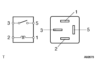 |
Remove the IG1 relay from the No. 3 relay block.
Measure the resistance of the relay.
| Tester Connection | Specified Condition |
| 3 - 5 | 10 kΩ or higher |
| 3 - 5 | Below 1 Ω (when battery voltage is applied to terminals 1 and 2) |
|
| ||||
| OK | |
| 3.CHECK WIRE HARNESS (MASTER SWITCH - BATTERY AND BODY GROUND) |
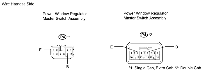
LHD:
Disconnect the P4 master switch connector.
Measure the voltage of the wire harness side connectors.
| Tester Connection | Condition | Specified Condition |
| P4-9 (B) - Body ground | Ignition switch ON | 10 to 14 V |
| Tester Connection | Condition | Specified Condition |
| P4-6 (B) - Body ground | Ignition switch ON | 10 to 14 V |
Measure the resistance of the wire harness side connectors.
| Tester Connection | Specified Condition |
| P4-1 (E) - Body ground | Below 1 Ω |
| Tester Connection | Specified Condition |
| P4-3 (E) - Body ground | Below 1 Ω |
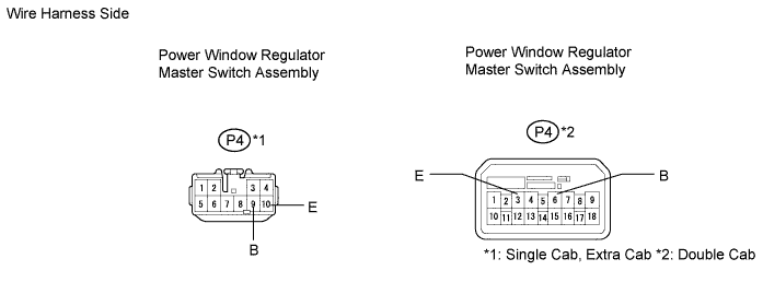
RHD:
Disconnect the P4 master switch connector.
Measure the voltage of the wire harness side connectors.
| Tester Connection | Condition | Specified Condition |
| P4-9 (B) - Body ground | Ignition switch ON | 10 to 14 V |
| Tester Connection | Condition | Specified Condition |
| P4-6 (B) - Body ground | Ignition switch ON | 10 to 14 V |
Measure the resistance of the wire harness side connectors.
| Tester Connection | Specified Condition |
| P4-10 (E) - Body ground | Below 1 Ω |
| Tester Connection | Specified Condition |
| P4-3 (E) - Body ground | Below 1 Ω |
|
| ||||
| OK | |
| 4.INSPECT IGNITION SWITCH ASSEMBLY |
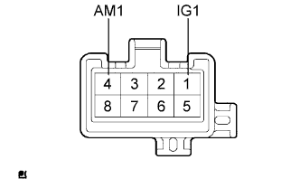 |
Remove the ignition switch.
Measure the resistance of the switch.
| Tester Connection | Switch Position | Specified Condition |
| 1 (IG1) - 4 (AM1) | OFF | 10 kΩ or higher |
| 1 (IG1) - 4 (AM1) | ON | Below 1 Ω |
|
| ||||
| OK | ||
| ||
