OUTPUT SHAFT > REMOVAL |
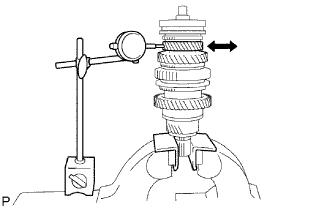
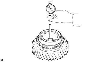
| 1. INSPECT 1ST GEAR THRUST CLEARANCE |
 |
Using a dial indicator, measure the thrust clearance.
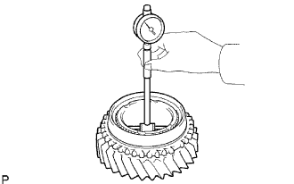
| 2. INSPECT 2ND GEAR THRUST CLEARANCE |
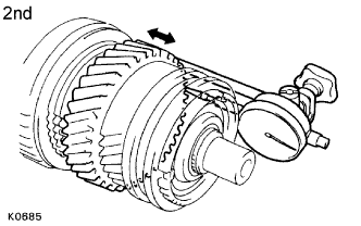 |
Using a dial indicator, measure the thrust clearance.
| 3. INSPECT 3RD GEAR THRUST CLEARANCE |
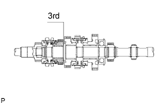 |
Using a feeler gauge, measure the thrust clearance.
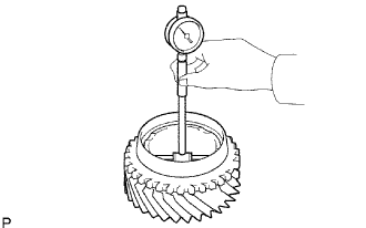
| 4. INSPECT 1ST GEAR RADIAL CLEARANCE |
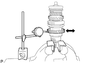 |
Using a dial indicator, measure the radial clearance.
| 5. INSPECT 2ND GEAR RADIAL CLEARANCE |
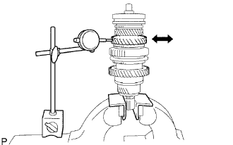 |
Using a dial indicator, measure the radial clearance.
| 6. INSPECT 3RD GEAR RADIAL CLEARANCE |
 |
Using a dial indicator, measure the radial clearance.
| 7. REMOVE SPEEDOMETER DRIVE GEAR |
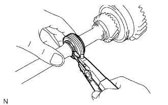 |
Using a snap ring expander, remove the snap ring.
Remove the drive gear.
Using a magnetic finger, remove the ball.
Using a snap ring expander, remove the snap ring.
| 8. REMOVE 1ST GEAR |
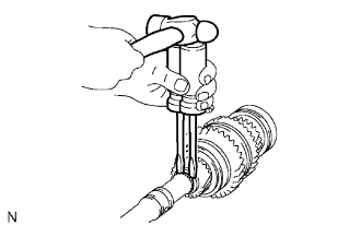 |
Using 2 screwdrivers and a hammer, tap out the snap ring from the output shaft.
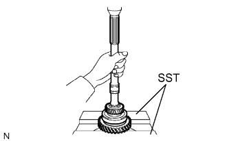 |
Using SST and a press, press out the 5th gear, center bearing, 1st gear, 1st gear needle roller bearing and 1st gear bearing inner race from the output shaft.
| 9. REMOVE NO. 1 SYNCHRONIZER RING (FOR 1ST GEAR) |
 |
Remove the No. 1 synchronizer ring (for the 1st gear) from the No. 1 clutch hub
| 10. REMOVE 1ST GEAR BEARING INNER RACE LOCK BALL |
 |
Using a magnetic finger, remove the lock ball.
| 11. REMOVE 2ND GEAR |
 |
Using SST and a press, press out the No. 1 clutch hub reverse gear, No. 1 synchronizer ring and 2nd gear.
| 12. REMOVE NO. 1 SYNCHRONIZER RING (FOR 2ND GEAR) |
 |
Remove the No. 1 synchronizer ring from the 2nd gear.
| 13. REMOVE 2ND GEAR NEEDLE ROLLER BEARING |
 |
Remove the needle roller bearing from the output shaft.
| 14. REMOVE NO. 1 TRANSMISSION CLUTCH HUB |
 |
Remove the 2 synchromesh shifting key springs.
Remove the reverse gear and 3 synchromesh shifting keys from the transmission clutch hub.
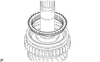
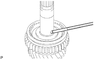
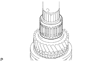
| 15. REMOVE 3RD GEAR |
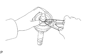 |
Using a snap ring expander, remove the snap ring from the output shaft.
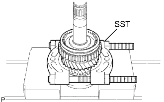
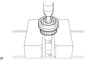 |
Using a press, press out the No. 2 clutch hub and 3rd gear.
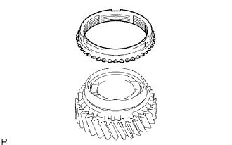
| 16. REMOVE NO. 2 SYNCHRONIZER RING |
 |
Remove the synchronizer ring from the 3rd gear.
| 17. REMOVE 3RD GEAR NEEDLE ROLLER BEARING |
 |
Remove the needle roller bearing from the output shaft.
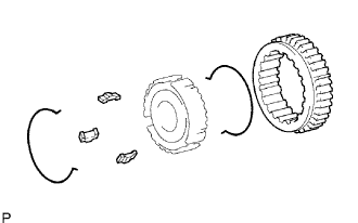
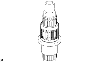
| 18. REMOVE NO. 2 TRANSMISSION CLUTCH HUB |
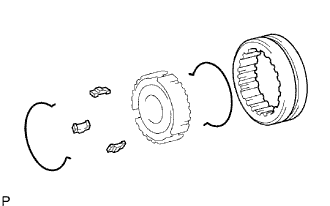 |
Remove the 2 synchromesh shifting key springs.
Remove the transmission hub sleeve and 3 synchromesh shifting keys from the transmission clutch hub.
| 19. INSPECT OUTPUT SHAFT |
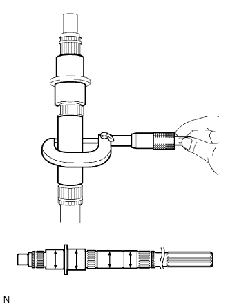 |
Using a micrometer, measure the outside diameter of the output shaft journal surface.
| Position | Outside diameter |
| Part A | 34.984 to 35.000 mm (1.3773 to 1.3780 in.) |
| Part B | 37.984 to 38.000 mm (1.4945 to 1.4960 in.) |
| Part C | 30.384 to 30.400 mm (1.1962 to 1.1968 in.) |
| Part D | 30.002 to 30.018mm (1.1812 to 1.1818 in.) |
 |
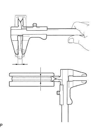
Using a micrometer, measure the flange thickness.
| 20. INSPECT 1ST GEAR BEARING INNER RACE |
 |
Using a micrometer, measure the inner race thickness.
 |
Using a micrometer, measure the outside diameter of the inner race.
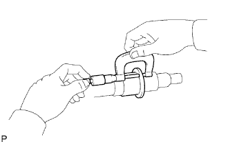
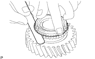
| 21. INSPECT NO. 1 SYNCHRONIZER RING (FOR 1ST GEAR) |
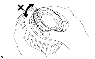 |
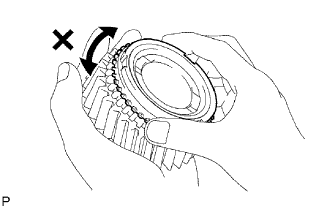
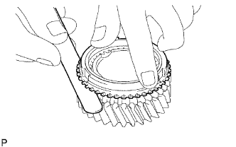
Coat the 1st gear cone with gear oil. Check the braking effect of the No. 1 synchronizer ring. Fit the ring to the shaft cone. Apply pressure to the ring and attempt to turn it both directions. Check that the ring locks.
Check again the braking effect of the No. 1 synchronizer ring.
 |
Using a feeler gauge, measure the clearance between the No. 1 synchronizer ring back and 1st gear spline end.
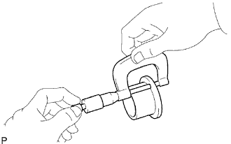
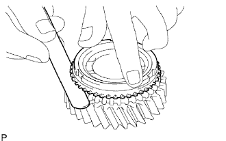
| 22. INSPECT NO. 1 SYNCHRONIZER RING (FOR 2ND GEAR) |
 |
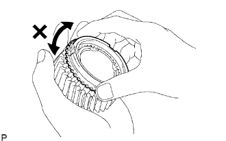
Coat the 2nd gear cone with gear oil. Check the braking effect of the No. 1 synchronizer ring. Fit the ring to the shaft cone. Apply pressure to the ring and attempt to turn it both directions. Check that the ring locks.
Check the braking effect of the No. 1 synchronizer ring again.
 |
Using a feeler gauge, measure the clearance between the No. 1 synchronizer ring back and 2nd gear spline end.
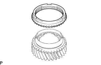
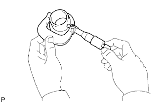
| 23. INSPECT NO. 2 SYNCHRONIZER RING |
 |
Coat the 3rd gear cone with gear oil. Check the braking effect of the No. 2 synchronizer ring. Fit the ring to the shaft cone. Apply pressure to the ring and attempt to turn it both directions. Check that the ring locks.
Check the braking effect of the No. 2 synchronizer ring again.
 |
Using a feeler gauge, measure the clearance between the No. 2 synchronizer ring back and 3rd gear spline end.
| 24. INSPECT REVERSE GEAR |
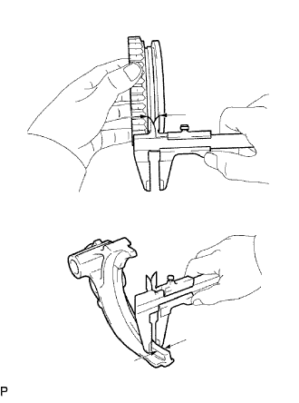 |
Using a vernier caliper, measure the clearance between reverse gear and No. 1 gear shift fork.
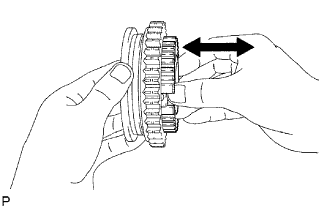 |
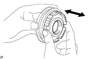
Check that the No. 1 transmission clutch hub and reverse gear slide smoothly.
Check that the spline gear's edges of the reverse gear are not worn down.
| 25. INSPECT NO. 2 TRANSMISSION HUB SLEEVE |
 |
Using a vernier caliper, measure the No. 2 hub sleeve and No. 2 gear shift fork as shown in the illustration.
 |
Check the sliding condition between the No. 2 hub sleeve and No. 2 clutch hub.
Check that the spline gear's edges of the No. 2 transmission hub sleeve are not worn down.
| 26. INSPECT 1ST GEAR |
 |
Using a cylinder gauge, measure the inside diameter of the 1st gear.
| 27. INSPECT 2ND GEAR |
 |
Using a cylinder gauge, measure the inside diameter of the 2nd gear.
| 28. INSPECT 3RD GEAR |
 |
Using a cylinder gauge, measure the inside diameter of the 3rd gear.
