COUNTER GEAR AND REVERSE IDLER GEAR > REMOVAL |
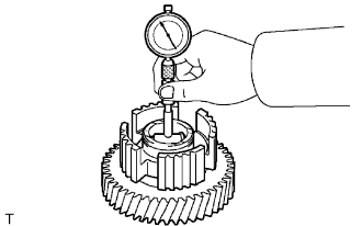
| 1. INSPECT COUNTER SHAFT 5TH GEAR RADIAL CLEARANCE |
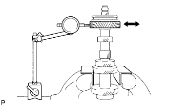 |
Install the 5th gear thrust washer lock ball, the 5th gear thrust washer and the 5th gear to the counter gear.
Using a dial indicator, measure the 5th gear radial clearance.
| 2. REMOVE COUNTER 5TH GEAR BEARING |
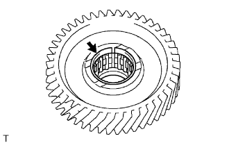 |
Remove the 5th gear bearing from the 5th gear.
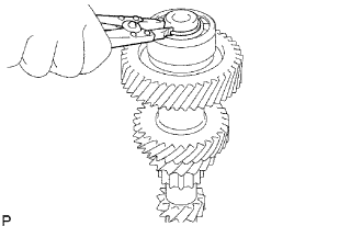
| 3. REMOVE NO. 3 TRANSMISSION HUB SLEEVE |
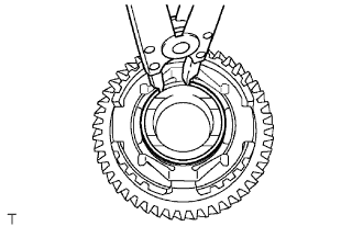 |
Using a snap ring expander, remove the snap ring from the 5th gear.
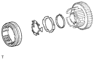 |
Remove the No. 3 hub sleeve, 2 No. 3 synchromesh shifting keys, key spring (return spring) and key spring (C spring) from the 5th gear.
| 4. INSPECT NO. 3 SYNCHRONIZER RING |
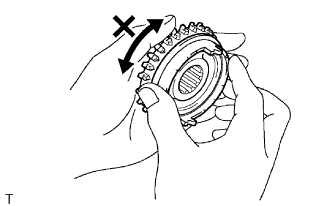 |
Coat the No. 5 gear spline piece cone with gear oil. Check the braking effect of the No. 3 synchronizer ring. Fit the ring to the shaft cone. Apply pressure to the ring and attempt to turn it both directions. Check that the ring locks.
Check the braking effect of the No. 3 synchronizer ring again.
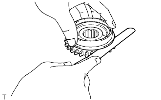 |
Using a feeler gauge, measure clearance between the No. 3 synchronizer ring back and the No. 5 gear spline piece spline end.
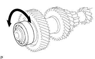
| 5. INSPECT NO. 3 TRANSMISSION HUB SLEEVE |
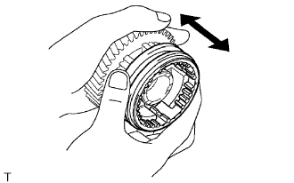 |
Check the sliding condition between the No. 3 hub sleeve and center shaft 5th gear.
Check that the spline gear's edges of the No. 3 hub sleeve are not worn down.
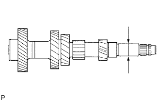
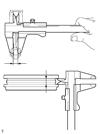 |
Using a vernier caliper, measure the No. 3 hub sleeve and No. 3 gear shift fork as shown in the illustration.
| 6. INSPECT COUNTER SHAFT 5TH GEAR |
 |
Using a cylinder gauge, measure the inside diameter of the 5th gear.
| 7. INSPECT COUNTER GEAR |
 |
Using a micrometer, measure the outside diameter of the journal surface.
| 8. INSPECT COUNTER GEAR FRONT BEARING |
 |
Make sure the front bearing rotates smoothly.
| 9. REMOVE COUNTER GEAR FRONT BEARING |
 |
Using a snap ring expander, remove the counter gear front No. 2 bearing snap ring from the counter gear.
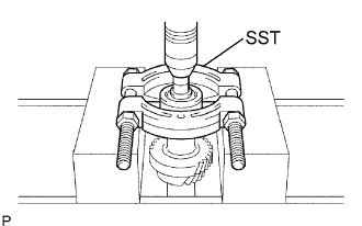 |
Using SST, a press and 14 mm socket wrench, remove the counter gear front bearing from the counter gear.
