INPUT SHAFT > REMOVAL

for Preparation Click here


HINT:
COMPONENTS: Click here


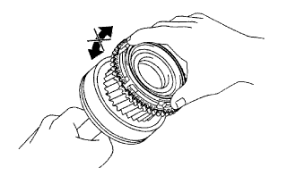
1. REMOVE NO. 2 SYNCHRONIZER RING


C067214E01
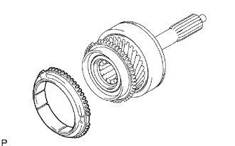
  1. Remove the synchronizer ring.


2. REMOVE INPUT SHAFT BEARING


C086536E01
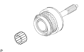
  1. Remove the 13 input shaft bearings.


3. REMOVE INPUT SHAFT FRONT BEARING


C086532E01
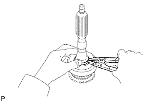
  1. Using a snap ring expander, remove the snap ring.


    C086533E01
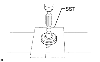
  1. Using SST and a press, press out the front bearing.

    SST
    09527-10011  


4. INSPECT NO. 2 SYNCHRONIZER RING


G037540E01
  1. Coat the input shaft cone with gear oil. Check the braking effect of the No. 2 synchronizer ring. Fit the ring to the shaft con. Apply pressure to the ring and attempt to turn it both directions. Check that the ring locks.

    1. If the braking effect is insufficient, apply a small amount of the fine lapping compound between the No. 2 synchronizer ring and the input shaft cone. Lightly rub the No. 2 synchronizer ring and the input shaft cone together.

    NOTICE:
    Ensure the fine lapping compound is completely washed off after rubbing.

  1. Check the braking effect of the No. 2 synchronizer ring again.


    C067456E01
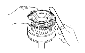
  1. Using a feeler gauge, measure the clearance between the No. 2 synchronizer ring back and the input shaft spline end.

    Standard clearance:
    1.00 to 2.00 mm (0.0394 to 0.0787 in.)

    1. If the clearance is not as specified, replace the No. 2 synchronizer ring and apply a small amount of the fine lapping compound on the input shaft cone.

    NOTICE:
    Ensure the fine lapping compound is completely washed off after rubbing.