MANUAL TRANSMISSION UNIT > INSTALLATION |
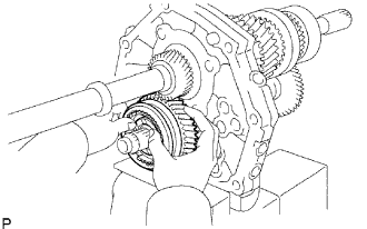
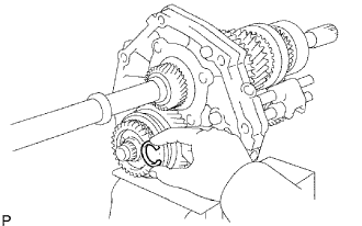
| 1. INSTALL OUTPUT SHAFT ASSEMBLY |
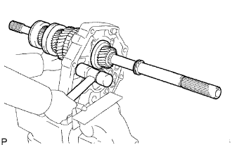 |
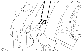
Install the output shaft into the intermediate plate by pushing on the output shaft and tapping on the intermediate plate with a plastic-faced hammer.
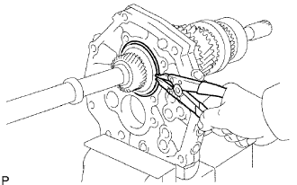 |
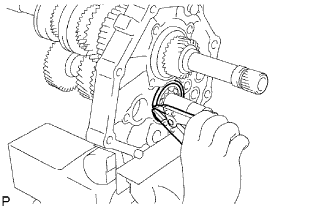
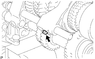
Using a snap ring expander, install the snap ring to the enter bearing.
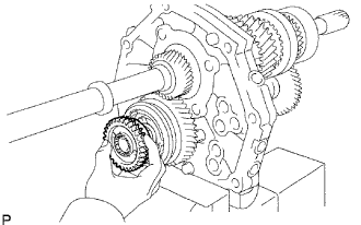
| 2. INSTALL COUNTER GEAR ASSEMBLY |
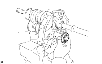 |
Coat the input shaft and the No. 2 synchronizer ring with gear oil.
Temporarily install the counter gear, input shaft and a new center bearing to the intermediate plate.
 |
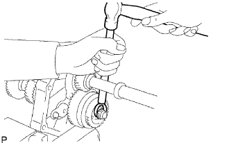
Using a plastic-faced hammer, install the center bearing to the intermediate plate by tapping the outer race to the counter gear center bearing.
 |
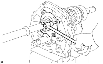
Using a snap ring expander, install the snap ring to the counter shaft center bearing.
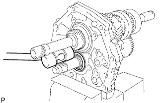
| 3. INSTALL OUTPUT SHAFT REAR BEARING RETAINER |
 |
Using a T40 "torx" socket wrench, install the rear bearing retainer to the intermediate palate with the 4 screws.
| 4. INSTALL REVERSE IDLER GEAR |
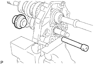 |
Install the idler gear shaft and idler gear to the intermediate plate.
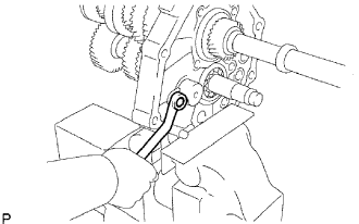 |
Install the idler gear shaft stopper to the intermediate plate with the colt.
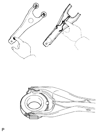
| 5. INSTALL REVERSE SHIFT ARM |
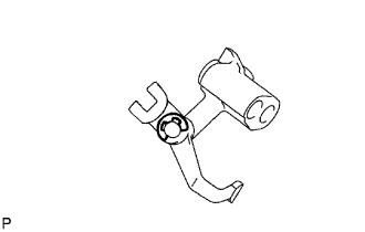 |
Install a new E-ring and the shift fork to the shift arm.
| 6. INSTALL REVERSE SHIFT ARM BRACKET |
 |
Install the arm bracket with the shift arm to the intermediate plate.
Install the 2 bolts.
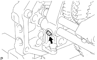
| 7. INSTALL 5TH GEAR THRUST WASHER LOCK BALL |
 |
Install the lock ball.
| 8. INSTALL 5TH GEAR THRUST WASHER |
 |
| 9. INSTALL COUNTER SHAFT 5TH GEAR ASSEMBLY |
 |
Install the 5th gear to the counter gear.
 |
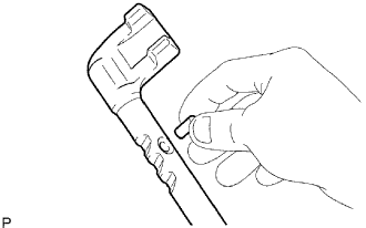
Temporarily install the No. 3 synchronizer ring on the No. 5 gear spline piece.
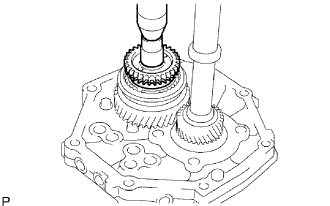 |
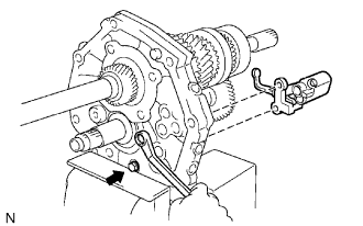
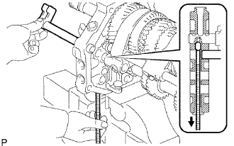
Dismount the intermediate plate from the vise.
Stand the transmission as shown in the illustration.
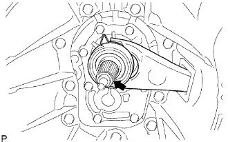
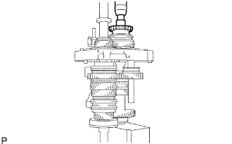 |
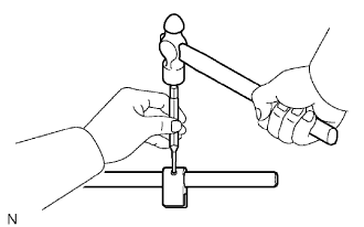
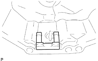
Using a press and 22 mm socket wrench, press in the No. 5 gear spline piece with the No. 3 synchronizer ring slots aligned with the shifting keys.
Mount the intermediate plate to the vise.
 |
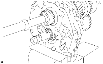
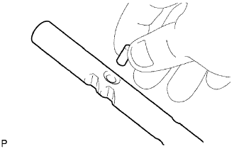
Select a snap ring that will allow minimal axial play.
| Mark | Thickness |
| A | 2.80 to 2.85 mm (0.110 to 0.112 in.) |
| B | 2.85 to 2.90 mm (0.112 to 0.114 in.) |
| C | 2.90 to 2.95 mm (0.114 to 0.116 in.) |
| D | 2.95 to 3.00 mm (0.116 to 0.118 in.) |
| E | 3.00 to 3.05 mm (0.118 to 0.120 in.) |
| F | 3.05 to 3.10 mm (0.120 to 0.122 in.) |
| G | 3.10 to 3.15 mm (0.122 to 0.124 in.) |
 |
Using a brass bar and hammer, tap in the snap ring to the counter gear.
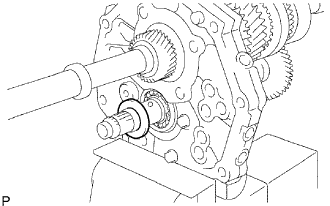
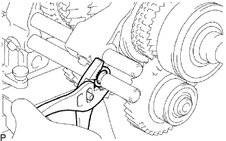
| 10. INSPECT COUNTER SHAFT 5TH GEAR THRUST CLEARANCE |
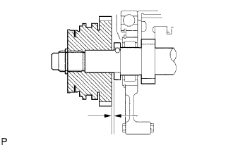 |
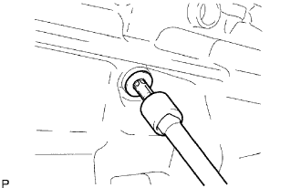
Using a feeler gauge, measure the thrust clearance.
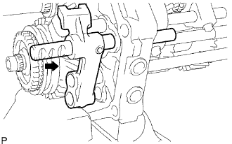
| 11. INSTALL NO. 2 SHIFT FORK SHAFT |
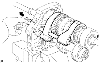 |
Install the No. 2 shift fork shaft through the No. 2 gear shift fork, No. 1 gear shift fork and intermediate plate.
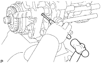
 |
Using a brass bar and hammer, tap in the shaft snap ring to the No. 2 shift fork shaft.
 |
Install the bolt to the No. 2 gear shift fork.
| 12. INSTALL NO. 2 SHIFT INTERLOCK PIN |
 |
Coat the No. 2 shift interlock pin with MP grease, and install it into the No. 1 gear shift fork shaft.
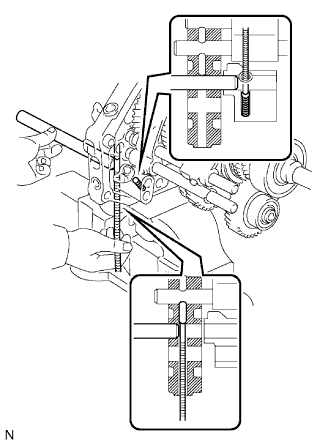
| 13. INSTALL NO. 1 SHIFT FORK SHAFT |
 |
Coat the No. 1 interlock pin with MP grease.
Using a magnetic finger, install the No. 1 interlock pin to the intermediate plate.
Install the No. 1 gear shift fork shaft through the No. 2 gear shift fork and intermediate plate.
 |
Install the bolt to the No. 1 shift fork.
 |
Using pliers, install the snap ring to the No. 1 gear shift fork shaft.
| 14. INSTALL NO. 3 HEAD GEAR SHIFT |
 |
Install the No. 3 head gear shift to the No. 3 shift fork shaft.
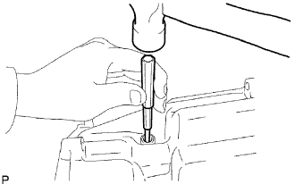
Using a 5 mm pin punch and hammer, tap in the slotted spring pin to the No. 3 shift fork shaft.
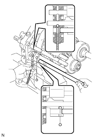
| 15. INSTALL NO. 2 SHIFT INTERLOCK PIN |
 |
Coat the No. 2 interlock pin with MP grease, and install it into the No. 3 shift fork shaft.
| 16. INSTALL NO. 3 SHIFT FORK SHAFT |
 |
Coat the ball pin shift interlock with MP grease.
Using a magnetic finger, install the No. 3 shift interlock pin to the intermediate plate.
Install the No. 3 shift fork shaft through the reverse shift fork and the intermediate plate.
Coat the shift detent ball with MP grease.
Install the shift detent ball and the shift detent ball low side compression spring to the reverse shift fork.
Install the No. 3 shift fork shaft through the reverse shift arm.
| 17. INSTALL NO. 5 SHIFT FORK SHAFT |
 |
Install the reverse shift head and No. 5 shift fork shaft.
 |
Using a 5 mm pin punch and hammer, tap in the slotted spring pin to the reverse shift head.
| 18. INSTALL NO. 4 SHIFT FORK SHAFT |
 |
Coat the ball pin shift interlock with MP grease.
Using a magnetic finger, install the ball pin shift interlock to the intermediate plate.
Install the No. 4 shift fork shaft through the reverse shift fork, intermediate plate and reverse shift head.
 |
Using a brass bar and hammer, tap in the shift fork shaft snap ring and 2 reverse shift head rings.
 |
Install the bolt to the No. 3 gear shift fork.
| 19. INSTALL NO. 2 SHIFT DETENT BALL |
 |
Coat the No. 2 detent ball with MP grease.
Install the No. 2 detent ball and compression spring to the intermediate plate.
 |
Coat the spring seat with sealant.
Using a T40 "torx" socket wrench, install the spring seat to the intermediate plate.
| 20. INSTALL SHIFT DETENT BALL |
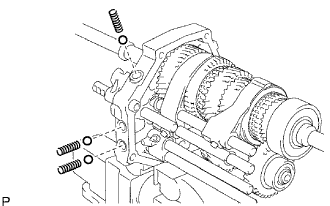 |
Coat the 3 shift detent balls with MP grease, and install them and the 3 compression springs to the intermediate plate.
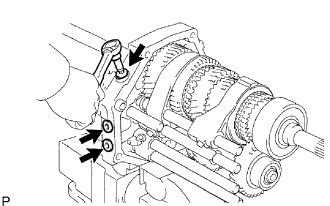 |
Coat the 3 spring seats with sealant.
Using a T40 "torx" socket wrench, install the 3 spring seats to the intermediate plate.
| 21. INSTALL MANUAL TRANSMISSION CASE |
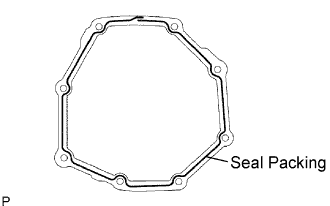 |
Apply seal packing to the transmission case as shown in the illustration.
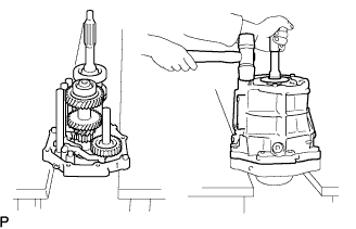 |
Stand the intermediate plate as shown in the illustration.
Using a plastic-faced hammer, install the transmission case to the intermediate plate as shown in the illustration.
| 22. INSTALL NO. 1 COUNTER GEAR FRONT BEARING SNAP RING |
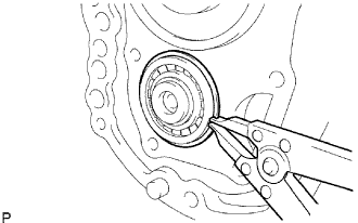 |
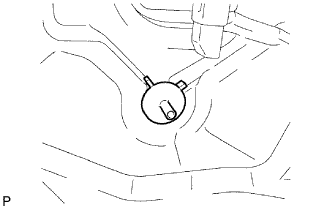
Using a snap ring expander, install the snap ring to the front bearing.
| 23. INSTALL FRONT BEARING SHAFT SNAP RING |
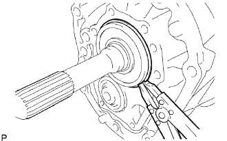 |
Using a snap ring expander, install the snap ring to the input shaft front bearing.
| 24. INSTALL TRANSMISSION FRONT BEARING RETAINER OIL SEAL |
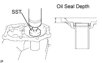 |
Using SST, press in a new oil seat to the front bearing retainer.
| 25. CHECK BEARING RETAINER FRONT |
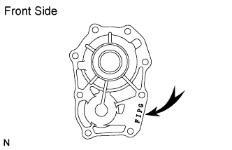 |
Check that "FIPG" is imprinted on the bearing retainer front.
| 26. INSTALL BEARING RETAINER FRONT |
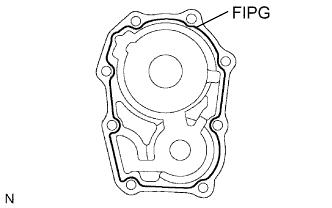 |
w/o Gasket:
Apply "FIPG" to the bearing retainer front as shown in the illustration.
w/ Gasket:
Install the bearing retainer front with gasket to the transmission case.
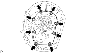 |
w/o Gasket:
Install the bearing retainer front with gasket to the transmission case.
Apply sealant to the bolt threads.
Install the 8 bolts.
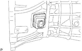
| 27. INSTALL EXTENSION HOUSING OIL SEAL |
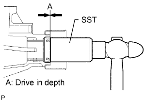 |
Using SST, tap in a new oil seal to the extension housing.
Lightly apply MP grease to the tip of the oil seal.
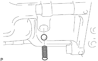
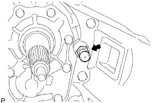
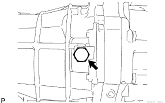
| 28. INSTALL REVERSE RESTRICT PIN |
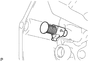 |
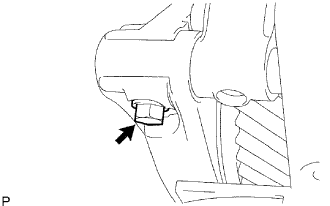
Install the restrict pin to the extension housing.
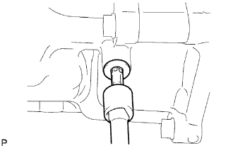
 |
Using a 5 mm pin punch and hammer, tap in the slotted spring pin to the extension housing.
 |
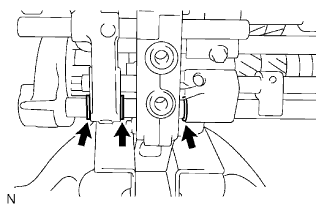
Using a T40 "torx" socket wrench, install the plug to the extension housing.
| 29. INSTALL OIL RECEIVER |
Install the oil receiver with the bolt.
| 30. INSTALL OIL RECEIVER PIPE |
 |
Install the oil receiver pipe to the extension housing.
| 31. INSTALL TRANSMISSION MAGNET |
 |
Install the magnet to the extension housing.
| 32. INSTALL EXTENSION HOUSING |
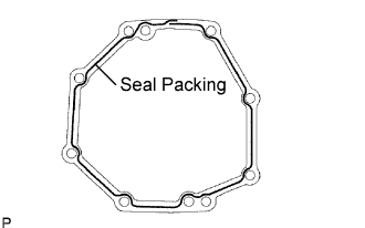 |
Apply seal packing to the extension housing as shown in the illustration.
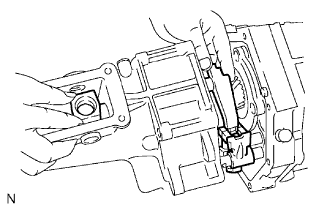 |
Install the shift and select lever to the extension housing.
Connect the shift and select lever to the shift fork shaft and put in the shift lever housing.
Align No. 5 shift fork shaft to the extension housing installation hole and push in the extension housing.
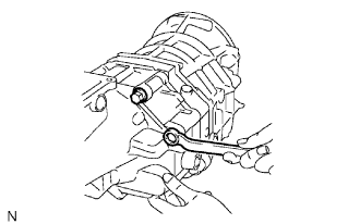 |
Install the extension housing to the manual transmission case with the 8 bolts.
 |
Install the bolt to the shift lever housing.
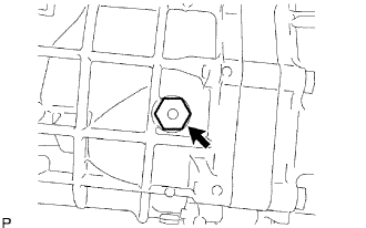
| 33. INSTALL SHAFT DETENT BALL |
 |
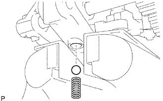
Coat the shift detent ball with MP grease, and install it and the compression spring to the extension housing.
 |
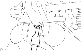
Using a T40 "torx" socket wrench, install the spring seat to the extension housing.
| 34. INSTALL SPEEDOMETER DRIVEN GEAR |
Install a new O-ring to the driven gear.
Install the driven gear with the bolt.
| 35. INSTALL CONTROL SHIFT LEVER RETAINER |
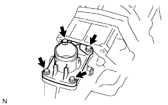 |
Install the oil deflector and shift lever retainer to the extension housing with the 4 bolts.
| 36. INSTALL RESTRICT PIN |
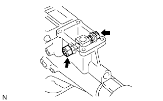 |
Install the 2 restrict pins to the extension housing.
| 37. INSTALL CLUTCH HOUSING |
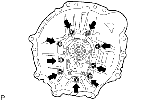 |
Install the clutch housing.
Apply liquid sealer to the bolt threads.
Install the 9 bolts.
| 38. INSTALL BACK-UP LIGHT SWITCH ASSEMBLY |
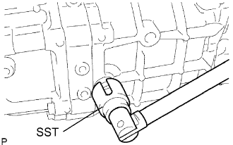 |
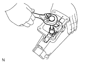
Using SST, install the back-up light switch to the transmission case.
| 39. INSTALL CLUTCH RELEASE FORK BOOT |
 |
Install the release fork boot to the clutch housing.
| 40. INSTALL RELEASE FORK SUPPORT |
 |
Install the release fork support to the clutch housing.
| 41. INSTALL CLUTCH RELEASE BEARING ASSEMBLY |
 |
Coat the release bearing with release hub grease, and install it to the release fork.
| 42. INSTALL CLUTCH RELEASE FORK |
 |
Install the release fork to the input shaft.
Apply molybdenum disulphide lithium base grease to the input shaft spline.
| 43. INSTALL DRAIN PLUG |
 |
Install a new gasket and the drain plug to the transmission case.
| 44. INSTALL FILLER PLUG |
 |
Install a new gasket and the filler plug to the transmission case.
