AUTOMATIC TRANSMISSION ASSEMBLY > INSTALLATION |
| 1. INSPECT TORQUE CONVERTER CLUTCH ASSEMBLY |
Inspect the torque converter clutch assembly (Click here ).
| 2. INSTALL TORQUE CONVERTER CLUTCH ASSEMBLY |
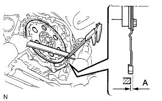 |
Install the torque converter clutch to the automatic transmission.
Using a vernier caliper and straightedge, measure dimension A between the transmission and the end surface of the drive plate.
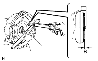 |
Using a vernier caliper and straightedge, measure dimension B shown in the illustration. Check that B is greater than A.
| 3. INSTALL TRANSFER ASSEMBLY |
Install the transfer assembly (Click here).
| 4. INSTALL NO. 1 ENGINE MOUNTING INSULATOR REAR |
 |
Install the engine mounting insulator to the transmission with the 4 bolts.
| 5. INSTALL AUTOMATIC TRANSMISSION ASSEMBLY |
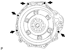 |
Install the transmission to the engine with the 5 bolts.
 |
Hold the crankshaft pulley bolt with a wrench and install the 6 torque converter clutch mounting bolts.
| 6. INSTALL STIFFENER PLATE |
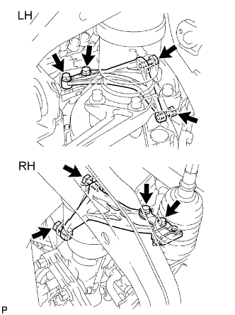 |
Install the No. 2 end plate.
Install the No. 4 cylinder block insulator.
Install the stiffener plate LH to the engine and transmission with the 4 bolts.
Install the stiffener plate RH (with clamp tube) to the engine and transmission with the 4 bolts.
| 7. CONNECT WIRE HARNESS |
| 8. CONNECT CONNECTOR |
Transmission side:
Connect the connectors.
Connect the temperature sensor connector.
Connect the park/neutral position switch connector.
Connect the 2 speed sensor connectors.
Connect the transmission wire connector.
Transfer side:
Connect the connectors.
Connect the indicator switch connector (4WD).
Connect the speedometer sensor connector.
Connect the indicator switch connector (L4).
Connect the indicator switch connector (neutral).
| 9. INSTALL NO. 3 FRAME CROSSMEMBER SUB-ASSEMBLY |
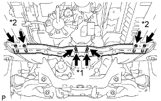 |
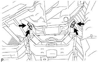
*2 Install the frame crossmember with the 4 bolts and 4 nuts.
*1 Install the 4 set bolts of the engine mounting insulator.
| 10. INSTALL STARTER ASSEMBLY |
Install the starter assembly (Click here).
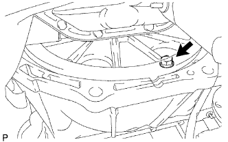
| 11. INSTALL TRANSMISSION CONTROL CABLE BRACKET |
 |
Install the control cable bracket with the 2 bolts.
| 12. CONNECT TRANSMISSION CONTROL SHIFT CABLE ASSEMBLY |
 |
Connect the control cable with the clip.
Connect the control cable with the nut.
| 13. INSTALL OIL COOLER TUBE |
 |
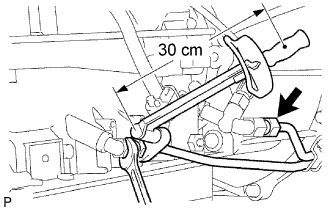
Loosely install the tip of the oil cooler tube inlet to the automatic transmission by hand.
Loosely install the tip of the oil cooler tube outlet to the automatic transmission by hand.
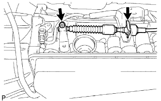
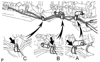
Install the 3 clamps with the 3 bolts.
 |
Using SST, tighten the inlet and outlet tubes.
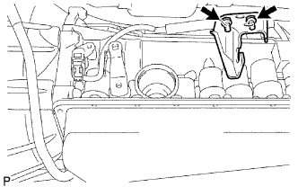
| 14. INSTALL TRANSMISSION OIL FILLER TUBE SUB-ASSEMBLY |
 |
Coat a new O-ring with ATF, and install it to the oil filler tube.
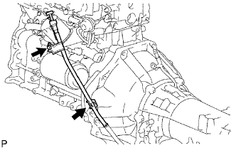
Install the oil filler tube to the transmission with the 2 bolts.
Install the oil level gauge.
| 15. INSTALL PROPELLER SHAFT WITH CENTER BEARING ASSEMBLY |
Install the propeller shaft with center bearing assembly (Click here).
| 16. INSTALL FRONT PROPELLER SHAFT ASSEMBLY |
Install the front propeller shaft assembly (Click here).
| 17. INSTALL TRANSFER CASE LOWER PROTECTOR |
Install the transfer case lower protector with the 4 bolts.
| 18. INSTALL FRONT EXHAUST PIPE ASSEMBLY |
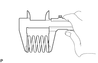 |
Using a vernier caliper, measure the free length of the compression spring.
Install the front pipe to the pipe support.
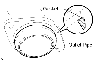 |
Install a new gasket to the outlet pipe.
Install the front pipe with the 2 compression springs and 2 bolts. Alternately tighten the bolts in several passes.
| 19. INSTALL TRANSFER HIGH AND LOW SHIFT LEVER ASSEMBLY |
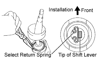 |
Install the transfer shift lever to the shift lever retainer.
Using needle-nose pliers, install the snap ring.
Install the shift lever boot with the 4 bolts.
| 20. INSTALL SHIFT LEVER BOOT ASSEMBLY |
Install the shift lever boot with the 4 screws.
| 21. ADJUST SHIFT LEVER POSITION |
Adjust the shift lever position (Click here).
| 22. ADD AUTOMATIC TRANSMISSION FLUID |
Add automatic transmission fluid (Click here)
| 23. CONNECT CABLE TO NEGATIVE BATTERY TERMINAL |
| 24. PERFORM INITIALIZATION |
Perform initialization (Click here).
| 25. INSPECT SHIFT LEVER POSITION |
Inspect the shift lever position (Click here).
| 26. INSTALL CONSOLE BOX ASSEMBLY |
Install the console box assembly (Click here).
| 27. CHECK FOR EXHAUST GAS LEAKS |
| 28. INSPECT AUTOMATIC TRANSMISSION FLUID |
Inspect the automatic transmission fluid (Click here).
| 29. INSTALL NO. 2 ENGINE UNDER COVER |
| 30. INSTALL NO. 1 ENGINE UNDER COVER |
