PARK / NEUTRAL POSITION SWITCH > INSTALLATION |
| 1. INSTALL PARK/NEUTRAL POSITION SWITCH ASSEMBLY |
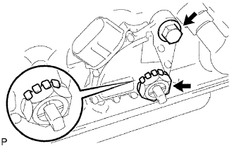 |
Install the park/neutral position switch to the manual valve shaft.
Temporarily install the bolt.
Install a new lock washer and the nut.
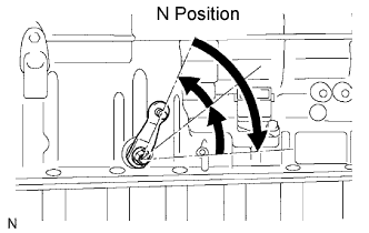 |
Push the control shaft rearward as much as possible.
Return the control shaft lever 2 notches to the N position.
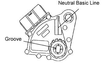 |
Align the neutral basic line with the switch groove, and tighten the bolt.
Using a screwdriver, bend the tabs of the lock washer.
| 2. CONNECT PARK/NEUTRAL POSITION SWITCH CONNECTOR |
| 3. CONNECT CABLE TO NEGATIVE BATTERY TERMINAL |
| 4. PERFORM INITIALIZATION |
Perform initialization (Click here ).
| 5. INSPECT SHIFT LEVER POSITION |
Inspect the shift lever position (Click here).
| 6. ADJUST SHIFT LEVER POSITION |
Adjust the shift lever position (Click here ).
| 7. INSPECT PARK/NEUTRAL POSITION SWITCH ASSEMBLY |
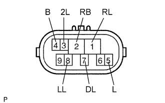 |
Measure the resistance of the park/neutral switch when the shift lever is moved to each position
| Tester Connection | Shift Lever Position | Specified Condition |
| 4 (B) - 5 (L) | P or N | Below 1 Ω |
| 4 (B) - 5 (L) | Not on P or N | 10 kΩ or higher |
| 1 (RL) - 2 (RB) | R | Below 1 Ω |
| 1 (RL) - 2 (RB) | Not on R | 10 kΩ or higher |
| 2 (RB) - 7 (DL) | D | Below 1 Ω |
| 2 (RB) - 7 (DL) | Not on D | 10 kΩ or higher |
| 2 (RB) - 3 (2L) | 2 | Below 1 Ω |
| 2 (RB) - 3 (2L) | Not on 2 | 10 kΩ or higher |
| 2 (RB) - 8 (LL) | L | Below 1 Ω |
| 2 (RB) - 8 (LL) | Not on L | 10 kΩ or higher |
